Flash Synth
18 Oct 2019Progress: Complete
A tiny, powered-by-MIDI, polyphonic FM synthesizer that supports full resolution pitchbend and microtonal tunings.
This project was built as a commission for Aaron Andrew Hunt. A production run is under way and the finished units will be sold on his site, H-Pi Instruments.
Video
The first half of the video is a demonstration of the synth, with the rest being a technical explanation. There is a transcript of the technical explanations at the end of this page.
Specification
The first thing we did was decide on what the synth should do:
- Fully polyphonic, meaning 16 voices for the standard patches. More complex patches could also be added at a reduced polyphony, but the main algorithms are aiming for 16.
- Full support for pitch bend. This means respecting the full 14-bit value (something most keyboards don't even send) and also working with the RPN pitchbend range adjustment messages. The synth is designed to work perfectly with the Tonal Plexus – Aaron's microtonal MIDI keyboard, which sends a pitchbend range of 1 semitone, to get the most accurate detuning of notes.
- Powered by MIDI. Pulling its power parasitically from the plug. This is the real stickler.
- High quality sound output. This means stereo and full audio bandwidth: I aimed for the standard samplerate of 44.1kHz.
- Produces as many "bleeps and bloops" as possible. Some people criticised my original Smallest MIDI Synth for only producing a square wave with no envelopes or filters. This synth needs to produce a repertoire of sounds big enough to silence such comments.
Hardware
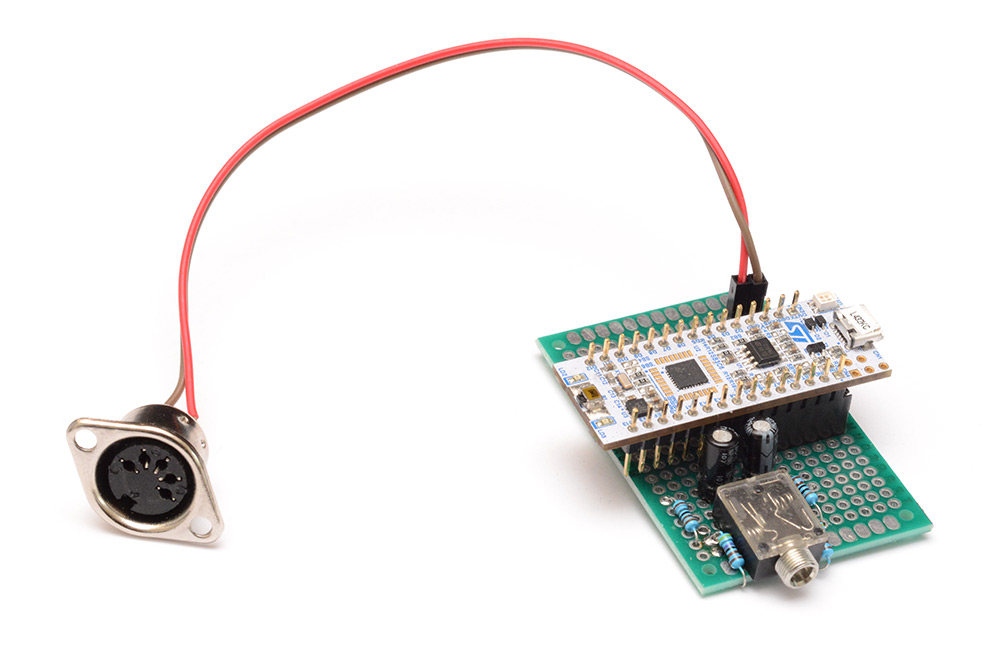
As I concluded with my last attempt at a polyphonic synth cable, the solution is to throw more processing power at it. Since there was no harm in trying, I threw an STM32F103 onto a board to see if we could power it with the midi signal. We could not.
This was a functioning synthesizer, that produced some basic square waves when MIDI arrived. The header on the right is a standard ST-Link connection, and it worked fine when powered from there. But when powered by MIDI, there was no hope here.
I next made a search for a more appropriate chip, and given the specification initially settled on the STM32L476RG. This has 1MB of flash memory, a built in DAC, everything we need...
Pretty astonishing what that chip can do, it's a super duper micro.
The datasheet gives a power consumption in terms of μA per MHz. There is also a fixed additional power consumption for any peripherals you enable. For instance, the DAC draws about 1.5mA. You can reduce this by disabling output buffering, but then the signal would be too weak for our use. Rather than peering through datasheets, I used the STM32CubeMX software. I really don't like it as a replacement for the older style peripheral libraries and example projects, but the power consumption calculator is exactly what we needed.
You can select which peripherals are in use and set the master clock speed, and see what the resulting amperage would be.
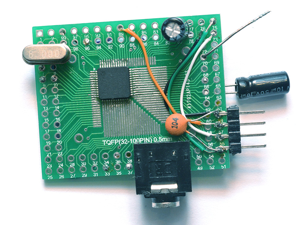
Convinced that this was going to work, I set about writing a basic synthesizer and powering it from MIDI.
As evident in the picture, the sound output was only mono at this point and my confusion over the behaviour of ceramic capacitors led to me sticking a bunch of them together in an attempt to get the needed capacitance on board.
This served as the prototype hardware for a while, and the basic synth was developed on it. I also used a dev board – the nucleo boards from ST are fantastic. They are actually the main reason that ST is one of my favourite companies. Other companies consider development kits as a revenue stream (I've used dev boards in the past which cost over $1000, plus licence fee for the software that goes with it) but ST has taken the opposite approach: they subsidise the dev boards! A development board for the STM32L476RG costs only a few pennies more than the bare chip on its own. Fantastic!
The dev board works well but the amount of extra hardware on there (there's a complete ST-link programmer, which would cost more than the dev kit if we bought it on its own) means that we couldn't test the powered-by-MIDI aspect with it.
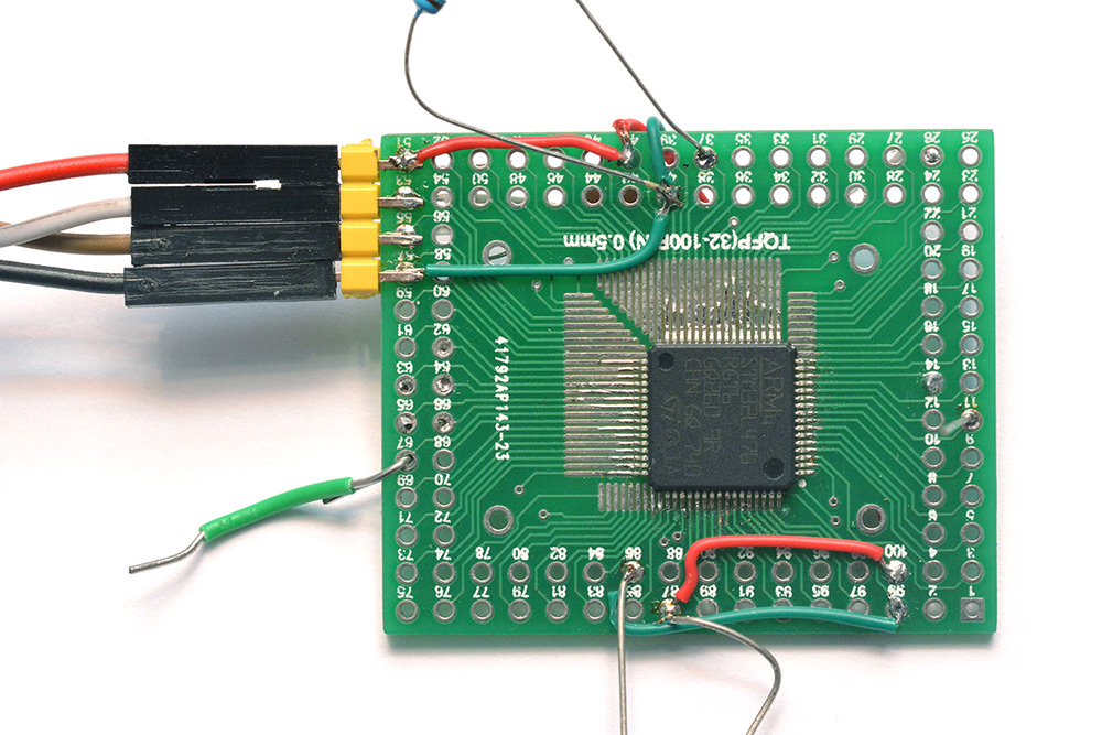
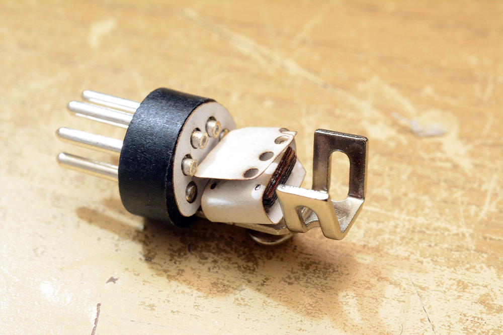
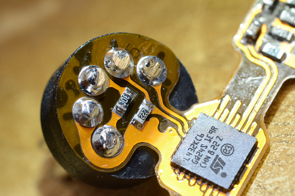
For various reasons I ended up switching to a smaller chip, the STM32L432KC. The physical size is a concern (the L476 was too big to fit into a midi connector) and also the power consumption of the L432 is marginally smaller. The code was quite easy to port, as the peripheral libraries are designed to make it so. Another reason for the switch was that the L476 was, to put it bluntly, overkill.
QFN part so no breakout board this time, just hand soldering with single strands of micro wire. In the above picture you can see I'm still struggling with the ceramic capacitor. I also, by the time this picture was taken, had decided on the bootloader protocol, using the extra pins of the DIN connector.
To solder the chip upside down, there are three strips of kapton tape, one inverted to provide a sticky surface, and two to hold that down. It takes a serious amount of concentration to solder a part upside down, many times in the past I have flipped the pinout incorrectly. Luckily in this case there are only a handful of connections.
The bootloader is effective, but for development purposes, where you want to repeatedly upload new versions of the code, a dev board is still better, because it means you don't have to keep unplugging the DIN connector.
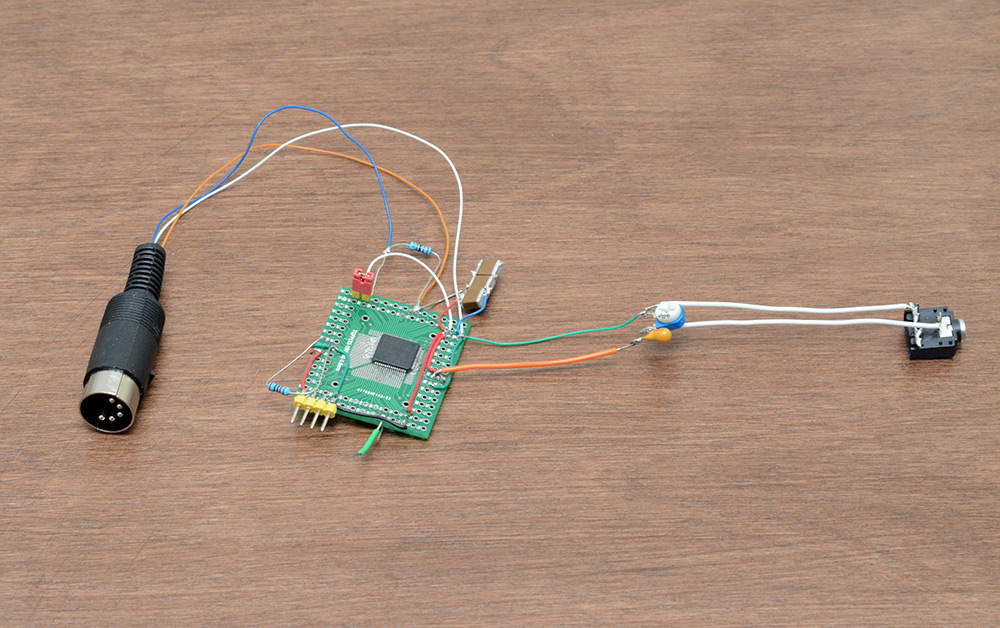
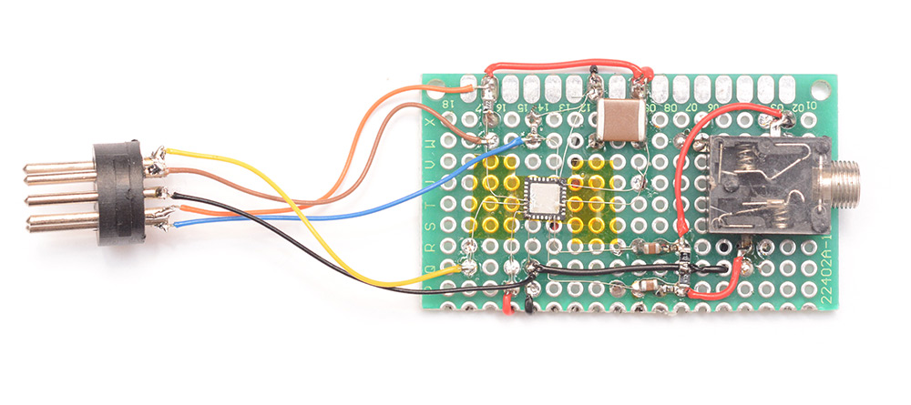
I stuck it onto some protoboard with the filter on the DAC output and a simple (i.e. unisolated) MIDI input. I could then develop the software and load it over the USB/ST-link on the board without needing to unplug anything.
Talking of the bootloader, the inital prototype, once I'd come up with the design was as simple as a DIN connector on a USB-UART adapter.
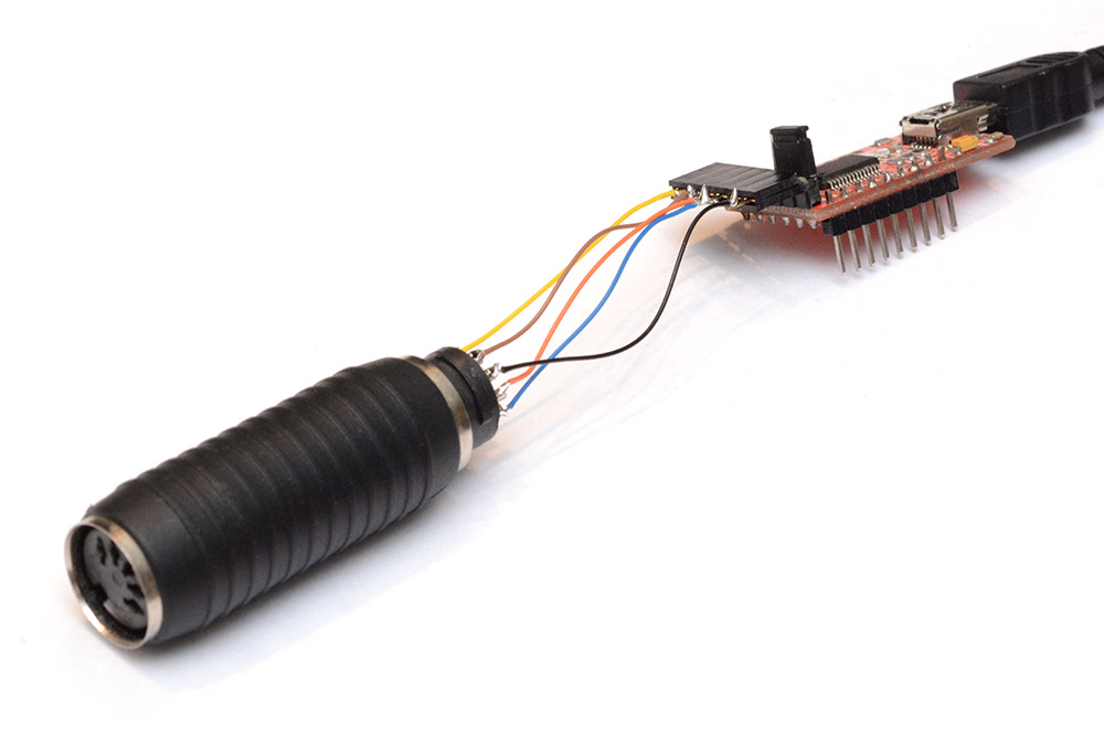
I didn't have a female DIN to hand, as you can see. It's just an FTDI board. I later added a small resistor (10Ω) inline to limit the inrush current of the large capacitor. Though I didn't experience this, without that resistor the FTDI chip could brownout and reset the connection when it's first plugged in. Another addition, planned for the production programming units, is software control over the power line. Being able to power cycle the chip through software is not a necessity, but it may make the system more robust.
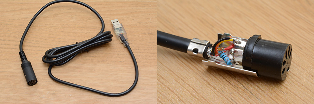
I then produced a usable programming cable by lopping the end off of an FTDI cable. There are a myriad variants of this type of cable, because of the configuration pins on the chip which can be wired up differently. It's very important to have a 3.3V logic level, and a 3.3V supply output from the FTDI chip's onboard regulator. Many cables labelled as "3.3V" are only referring to the signal levels.
With all of the hardware decided on, the final thing was to compress it into the housing. There was no doubt that a flexible PCB was the answer, but first let's look at the software side of things.
Software
As explained in the video, I opted not to write the code in assembly. Straight C, with the included peripheral libraries. The peripheral libraries are now split into HAL (hardware abstraction layer) and LL (low-level). I am, if I am honest, completely unhappy about the way the peripheral libaries are implemented. The code generated by STM32CubeMX drives me nuts, but the two things that are a real disgrace:
- The peripheral configuration operates at run-time. What could and should be done at compile time is done in a way that eats up some of your resources. It's a minor hit, but it's still a hit and kinda inexcusable. The reason it's done this way is apparently for compatibility, so that the same code can run on different chips. I would have much rather sacrificed that for a lighter-weight peripheral library.
- The abstraction level has hit a hazy middle ground which manages to encompass the worst of everything. As an example – say you wanted to enable a GPIO pin as output and set it high. Nothing could be conceptually simpler. But if you use the HAL library, and specify that a pin should be an output and its value is high, nothing will happen, because the pins will only function if the RCC clock source to that GPIO block has been enabled. Unbelievable! If you need register-level knowledge of how the chip works in order to use it, it's not much of an abstraction library. Couple that with the fact that the syntax is verbose and ugly, and it's hard to think of a worse way of implementing this thing.
With that rant out of the way, the first challenge was to enable the DAC output at the correct sample rate. This means using a timer and DMA to send data at the correct rate, and use the interrupts to re-fill the buffer. The way that double-buffering is implemented is by using a half-transfer complete interrupt, essentially splitting the memory in two, and filling the other half as one of them is being read out.
Lookup tables
The chip has, at full speed, just enough processing power to generate sixteen sine waves (using a recurrence relation) at frequencies calculated by calling pow(). This was quite exciting, because replacing that with lookup tables will free up plenty of power for actual synthesis. The lookup tables were designed as follows:
- A 512 byte (128 * float32) table for base frequencies in equal temperament
- A 32kB (8192 * float32) table as a sine wave lookup (more on this in a bit)
- A 64kB (16384 * float32) table for pitch bending. The entire table covers +/- one semitone, and offers the highest resolution pitchbending possible.
You may find the size of the pitchbend lookup table quite ridiculous, but it's the only way of achieving a 14-bit bend value at a reasonable speed. While most ears (mine included) can only hear a difference in pitch of about 5 cents (5% of a semitone), and this table resolution allows for pitch differences of around 0.01 cents, it's not quite that simple. Microtonal stuff implies microtonal chords, and when chords are involved there can be beat frequencies that reveal much finer differences.
For bend ranges of greater than a semitone, my plan was to count the number of places along in the equal temperament table, and add the fractional bend offset to that. This works magnificently, but more problems arise when we get into custom tuning tables. It's not even clear what the correct behaviour should be in this case – should a full bend stop at the next value in the table? Or detune it by exactly 1/12th of an octave? The latter is what I went for, although I may reconsider this in the future. At the moment, while using custom tuning tables, the pitch bend wheel detunes by one equal-temperament semitone.
A further lookup table of 32kB was added into RAM. Remember that the total RAM is only 64kB so this is hugely expensive. It functions as a secondary wavetable. The idea is to minimise the overhead in generating waves. By oversampling a smooth waveform, we reduce the importance of interpolation, and if we oversample enough, we don't need to do any interpolation at all. So, when a wave other than sine is loaded into RAM, we can pre-process the antialiasing needed and then just downsample to the right wavelength. This is my personal solution to the problem. It isn't perfect, more desirable would be to have multiple tables for different octave bands (which need more, or less, antialiasing) and blend between them. But it's perfectly usable, and apart from the memory usage the overhead is almost nothing.
In order to achieve the crunchiest square waves at the low end, and have perfectly alias-free square waves at the top, the solution is to have multiple square waves of different softnesses that can be selected.
Linker Troubles
I had a few problems with the makefile generated by STM32CubeMX. For one, the dependencies were not configured correctly. A.d file is supposed to be used to keep track of this stuff, and although it was generated it was not being read back. I think this was simply a typo on behalf of whoever wrote that makefile template.My goal in using the bootloader to also change patches and tuning tables was simply to locate them at a fixed position in the flash memory, somewhere at the end. The ease with which you can do this in assembly makes the ludicrous number of hoops one has to jump through with C even more painful. Some compilers have a directive to locate variables at certain positions in memory. I wish GCC had that. Instead we we have to add extra sections to the linker script and add attributes to variables to say which section they belong to.
One of the most interesting of my additions to the makefile was a post-compilation "visualization" step. We've already generated a .bin file with the exact map of program memory, so with the following line:
$(BUILD_DIR)/%.pgm: $(BUILD_DIR)/%.bin
	(echo "P5 256 1024 255" ; cat $< ) > $@
we generate a .pgm file. The header there is as simple as it could be to specify this is a binary format bitmap image, of 256 by 1024 pixels, with greyscale values of 0 to 255. With this we get an instant visualization of memory usage whenever we hit compile:
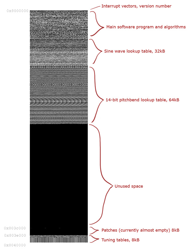
The annotations were added manually, of course, and at the point of this image the firmware was not yet finished, but it gives a pretty great overview of memory usage.
Another C/ASM problem. With multiple algorithms handled by function pointers, there are bits of RAM which get used only at certain times. For instance, the oscillator list for the main algorithm will not get used when an arpeggiator algorithm is loaded. In ASM, I would re-use the memory for each algorithm because it's dead simple to do, but in C you need to construct explicit unions between memory structures, and then addressing them becomes a chore. The solution is to use macros to address them, but even so this is a terribly ugly solution. There are other ways of doing it (do it all by direct memory addressing, perhaps) but I can't help but feel these problems wouldn't exist if we were writing in assembly.
Graceful Theft
An important point with polyphony is that when we do hit 16 voices at once, the synth continues to work. Beyond the voice limit, we need to "steal" voices from held notes so that new notes are not missed. The simplest algorithm here is to steal the oldest notes. An improvement on that is to preferentially steal notes of the same note-number. This specifically targets a type of playing where, for instance, you hold the sustain pedal and play a chord repeatedly.I implemented that without any trouble, but later, as I added the envelope controls, I found it to be unsatisfactory. If you have a long attack envelope, what should the stolen voice do? If we skip the attack, it sounds jarring. But if we jump to zero amplitude with the new note, an audible click will be introduced, which in some ways is worse.
After thinking for some time on the issue, I decided that the right thing to do is to gracefully release the note we're stealing, before starting the new note from zero. This means slightly delaying the new note, by a single buffer length, and in that buffer fading out the old note. The practicalities of implementing this add a huge amount of ugliness to the already heavily optimized envelope code, but the end result is that notes are stolen with a finite release time, and attack times are maintained, which sounds the least bad of the possible options.
Another release issue involves the arpeggiator. Previous synths of mine have not used long release times with arpeggiators. When you play a chord and let go, the desirable behaviour is to continue that chord as it releases, but initially all that happened was the single last note to be released continued to play. Unless you use the sustain pedal (which is a valid option) it's almost impossible to release a chord instantaneously, so there'll always be a last note that swallows the release.
To fix this, I added a release catch, of variable length (currently set to about 20ms) where any notes released in that time are remembered. If all notes are released within the catch time, the chord is restored so it sounds correct. To do this was more effort than you might imagine, since the chord not only has to restore the notes but also the order they were played in.
Another arpeggiator extension ensures that arpeggiation can happen between channels. Since the Tonal Plexus sends chords spread on different channels, this needed to be supported. Luckily, while arpeggiating, we have a surplus of processing power since we're effectively only using one voice.
Output volume
Our DAC is 12-bit. This is a fair bit below the "CD quality" of 16-bit, and at low amplitudes we risk quantization noise from the low bit depth. This poses quite a problem because for polyphony, we need to drop the wave peak-to-peak levels enough that the output doesn't clip. A simple approach is to put a hard limit on wave amplitude at 1/16th of the output voltage, but given that the parasitic power is already giving us a weak voltage, this makes the output level pretty quiet. And not all algorithms use the full 16 voices, so they could be made louder.The best solution would be to add an automatic gain control to the output, but because we're running in real time, we can't do look-ahead, so the attack time of our compressor would have to be zero, or perhaps a single buffer. I have yet to try what this sounds like, but I feel that if I did add it, we'd need a way of turning it on and off. A simpler solution is to give an output-gain control to the user, but this risks clipping the output, which would lead to horrid-sounding integer overflow (unless we manually clamped it). For now, I've left it like that, but at some point later I may have another stab at the automatic gain control.
Saving patches
One of the irritating things about being powered by MIDI is that you can't depend on the voltage being a certain level, or the available current being sufficient. So one of the features I most want to add to the synth but have not yet done so is the ability to save patches. You can load new patches via the bootloader of course, but if you find a nice sound while you're playing, it would be so much nicer to simply hit "save".We're able to write to the flash memory, but doing so on a dodgy power supply is simply too risky. Re-writing flash memory means erasing a page and writing it back. With the power supply we have, there is a big risk of corrupting the memory and ruining all of the patches, or worse, requiring a re-flash of the whole chip.
But – I haven't actually tried it. So maybe I'm terrified of nothing. The usefulness of being able to save patches on the spot would possibly justify the risk.
Algorithms
I will write a full instruction manual explaining these soon. But in short:
- Algorithm 1 is a straight 2-operator FM synth, with additional LFO. Polyphony of 16, but in dual- and quad-oscillator modes, the polyphony is reduced to 8.
- Algorithm 2 is an adaptation of an earlier algorithm I wrote for my Reverse Oscilloscope project, which I called PseudoFM. There is no FM ratio in this one. The polyphony is the same as with the first algorithm.
Most of the "moist" sounds are made with the second algorithm.
You may notice in the video an effect similar to reverb, but in fact this is entirely faked by means of an extension algorithm. The trick is to add a long release envlope, and inject phase noise into the oscillator as it releases. This again is a technique I came up with years ago and I have a soft spot for it in my heart. In an attempt to minimise the number of knobs required, I've added a switch to the LFO-speed control. When set to the maximum speed, the LFO is disabled and the phase-noise injection takes over (then controlled with the mod wheel).
There is room on the chip for dozens of extra algorithms, which can be downloaded once I've written them.
Flex PCB
Right, while we were developing the software the hardware design continued.My method of designing flex PCBs is to first make a paper template. Having your own laser cutter really pays off for something like this, being able to quickly export the PCB and chop it out of paper exactly. It only took a couple of iterations to settle on a design that would fit inside the housing (based off of a commercial DIN connector).
Stacks of thin card simulate the components. The first flex PCB had some problems I didn't anticipate, because I'd opted not to add a stifner board under the chip. The solder joins were prone to cracking when the board was flexed. I fixed this by adding relief into the design of the ground plane, so that the flexures were more clearly positioned. The first design probably would have been fine as we're not planning to open and close this more than once, but it's worth having the safety factor.
Some flux cleaner is still visible in the shot above, yet to evaporate.
The reduced copper on the flexing parts is accompanied by drawing out the pads of unused pins into traces that go nowhere. In the first design, the pads all terminated at the boundary of the chip, meaning there was a line along the board with no copper in it except for the two pins that were used, leading to a concentration of stress in them.
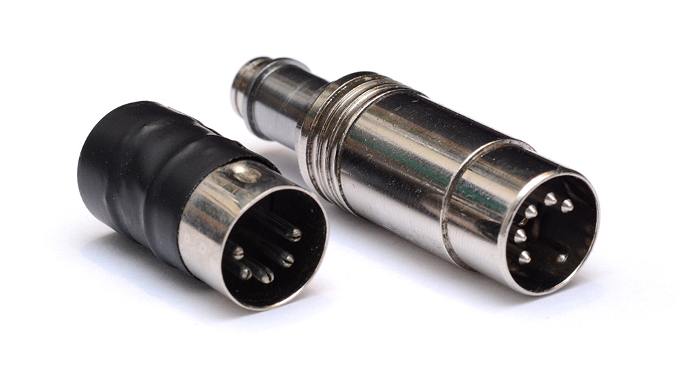
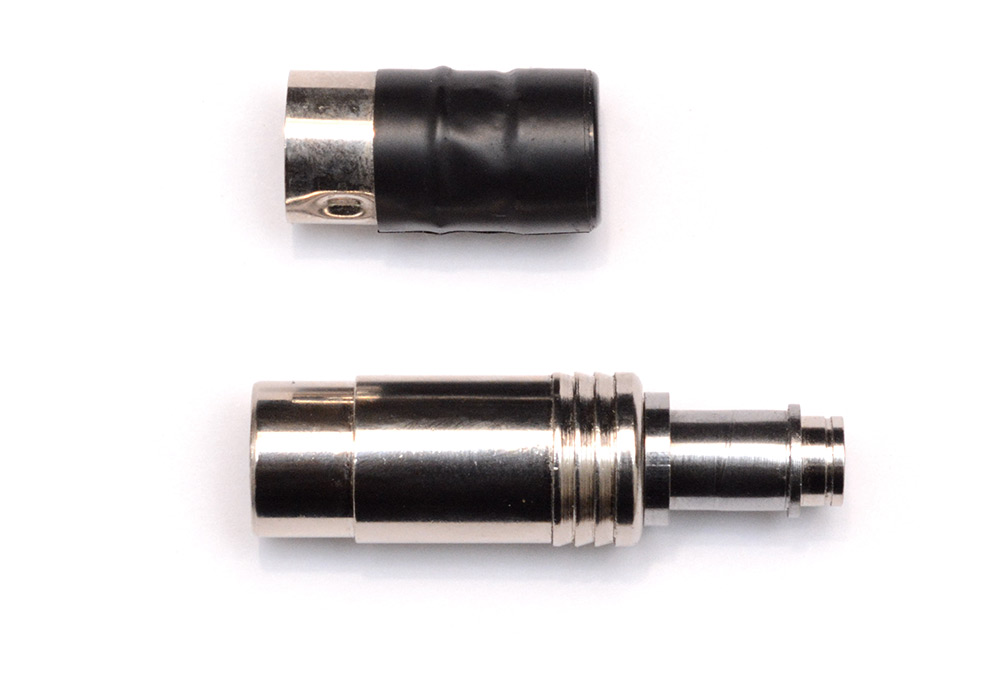
The enclosure is based on two commercial connectors, and a machined metal section that joins them.
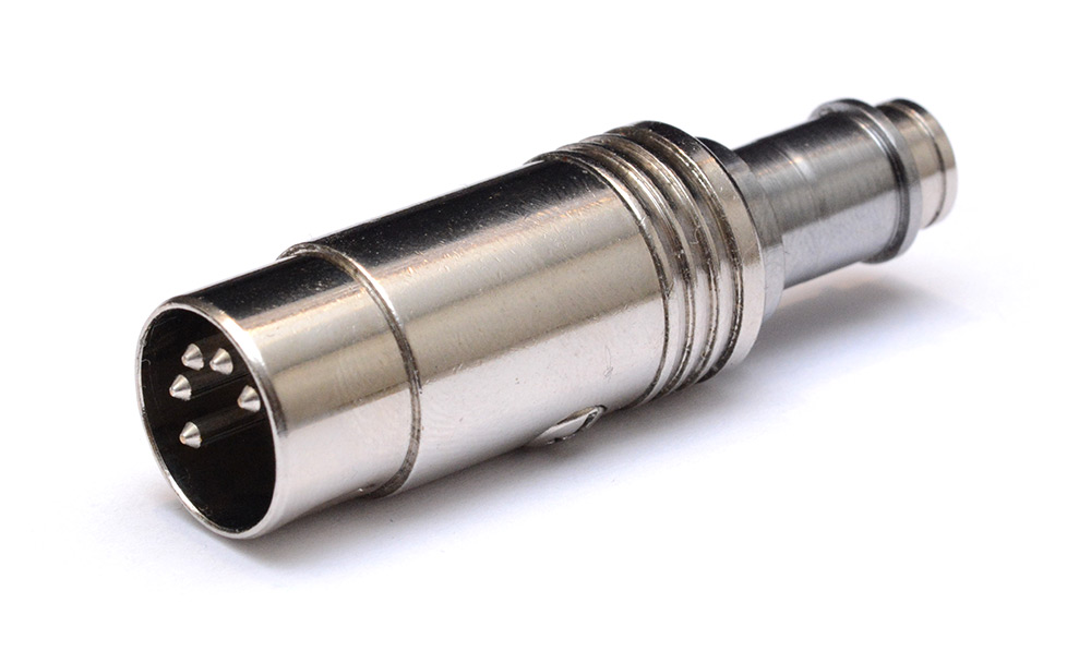
This should make for a more durable housing than the plastic-and-tape of the original Smallest Synth (which, to be fair, has held up spectacularly well).
Yum!
Technical details discussed in the video
You can load new patches. You can load new algorithms. You can upgrade the firmware. You can load custom tuning tables. All of these are possible with minimal effort because of how I've implemented the bootloader.The number one question here is: why didn't we stick a USB port on it? And the number one reason is... aesthetics. To me there's a certain beauty about a tiny package that turns DIN into TRS. If we had a USB port, for one, people would expect it to be a supplementary power supply, which means adding a mechanism to switch power sources that doesn't compromise the parasitic power in any way. Not difficult, of course, but it would add to the bulk of the circuit board. (And don't get me started on ground isolation...) We'd also want the USB port to act as a USB MIDI interface, and also have an automatic method of switching between DFU and USB-MIDI. And don't forget the physical difficulty of fitting a USB port into the design of the enclosure. All of this is doable but it's tedious to implement and at the very least would increase the development time. So I said, forget the USB port.
Right, so how else can we talk to the chip? MIDI sysex comes to mind, but let's just remind ourselves that MIDI runs at ~31kbps and sysex encapsulates 7 bytes for every 8 sent, and the flash memory in our processor, well originally we were aiming for one megabyte. Sending one megabyte over sysex is going to take many minutes. But far worse than the fact it's slow is the fact it's uni-directional, which means there's no feedback and no acknowledgement. You don't know if it's finished writing a page and you don't know if the checksums matched, so all you can do is add delays and when you get to the end of your 20 minute transaction you may find it failed on the first byte and you have to do it all again. So for me, MIDI sysex firmware updates are right out.
But there's another problem that affects *any* bootloader that speaks the same protocol as the application, if the transaction is interrupted, if the memory is corrupted, there's a risk that the chip ends up unbootable: or as some people say, bricked. There are defences against this, the most common technique is to double the amount of memory on board, and always keep a complete backup copy of the working firmware that the bootloader can recover from. But that's ugly (remember that more memory means more power consumption), it's a lot of work and it still doesn't entirely guarantee that the device is unbrickable.
The best defense against bricking is to use a ROM bootloader. The chip inside of here, spoilers, it's an STM32, like most microcontrollers in its class contains a ROM bootloader, that is a bit of code that cannot be overwritten, that contains a multi-protocol bootloader triggered by a hardware condition. Given the hardware condition, sparing actual damage to the circuit, that bootloader will never fail to run.
So I was looking at these extra pins, these are not used in the MIDI standard, they're specified to be there purely for "future use". The middle pin is a ground pin, for shielding purposes, and the other two pins are your current loop. My first thought was, could we make these two extra pins... the differential pair for the USB connection? And... I never did make my mind up about whether that would work. The problem is, what do you do with the 5 volts? Put it into the same power pin? We'd need to add a 3.3 volt regulator, and do it in such a way that it's completely off when the chip is powered parasitically. What seemed like a simple problem turned out to be a nightmare.
But. But. If we go back to using a UART bootloader, and we write our synthesizer so that its normal MIDI receive happens on the same UART hardware that the bootloader uses, they can share the RX pin. Then we've only got two things to add, the TX, and the hardware condition that triggers everything. Conveniently enough, we've got two unused pins in the DIN connector. Here's the clever bit: in MIDI mode we run at the standard 31 kilobits per second but when the bootloader is triggered we can ramp up the baud rate as high as it'll go, and because it's now bidirectional we've got acknowledgements and verification.
For the production run, there'll be a programming box that you plug it into, but for now I'm just using a USB serial adapter. Apart from the FTDI chip at one end, it's not an active cable. All I've had to do is cut the end off and put a DIN connector on it. You plug the synth in, you can read and write patches, you can change the tuning tables, you can do a firmware update, and even if you pull it out halfway through, it'll never get bricked because plugging it back in re-triggers the bootloader. (Thumbsup). By the way this cable does not function as a USB MIDI interface. Well, it could do, but it would be terrible, because these serial chips do not use the audio streaming class, they use the bulk transfer descriptors which have terrible latency.
Power delivery
First of all this whole 5mA thing is a myth. Yes, the spec is going for a 5mA current loop, but we're not using the same return path, we're returning through the shielding ground, and because the spec asks for an equal split on the output impedance we've immediately got twice as much current available. Maxmimum power would be delivered if we matched our input impedance to the output impedance (of 220Ω and ground) and in that case we'd get 11mA.I do know that there's a 3.3V MIDI spec, which compensates by having a lower output impedance, so that would let us draw more power, but the vast majority of devices use the original spec so we have to go by that. If we reduced our impedance we'd get more current, but if we increased our impedance we'd get more voltage, and voltage is important because our peak-to-peak output waveform is going to depend on that. The sound quality will depend on the stability of our power supply. Our processor is not a resistor, it's a constantly changing impedance and if we stray near that 11mA number it will make an audible buzz. We don't want that.
Capacitors
In the video I show a couple of ceramic capacitors, including one of the biggest surface mount ones you'll ever see, at a hundred microfarads. Sounds great, but this type of capacitor is useless for our project. We use ceramics all the time for filtering and decoupling and they work really well because of their lower series resistance, but you may not know that ceramics have a much less desirable characteristic. Their capacitance is a function of bias voltage. There are different chemistries for ceramic capacitors, some of the newer ones are much better but in general, as you approach the voltage rating you lose more than half of your rated capacitance. If you want the smallest size and the best characteristics, the type of capacitor you want is TANTALUM.Not that the polarity band on an electrolytic capacitor represents the cathode. The polarity band on a surface mount tantanlum capacitor represents the anode. Don't get them confused.
Choosing a chip
I knew from the start I wanted to use one of the STM32L4 series, the ultra-low-power microcontrollers, and if you've ever looked into this you'll know there are hundreds of variants. We want the most processing power for the electrical power available. The number we're looking at is not milliamps, but microamps per megahertz. The current consumption is a function of how fast you clock the processor and you can change the PLL settings while it's running. So as long as we're in the right ballpark, we can tweak the clock speed to match the power available.We want a chip with a built-in stereo DAC – that makes things so much easier – and a floating point unit with single cycle multiply. Surprisingly that doesn't limit our search very much, so we just go for the chip that has the lowest power consumption out of those results, which turned out to be, at the time of my search, the STM32L432.
ARM is a strange architecture. ARM processors, and the arm-gcc toolchain have evolved together, like they're intertwined. Changes in the hardware reflected in software, but also changes in software reflected in hardware. One of the things that sticks out to me with ARM microcontrollers is the ratio between ram and flash. Older microcontrollers tend to have 32 or 64 times as much flash memory as they have ram. Even like, a desktop computer, I don't know what the current specs are but my slightly old laptop has a terrabyte SSD and 16 gig of ram, so that's a ratio of 1 to 64. But these ARM micros have ratios of around 1 to 4. Relatively speaking, it's a huge amount of ram. I think the reason for that is how you're expected to program them – using the toolchain they provide.
They really don't want you to program in assembly. Everything is designed to work with their toolchain and there is no support at all for baremetal assembly. Couple that with the fact we're doing floating point stuff, so tweaking algorithms and playing with sounds would get incredibly tedious if it was all vfpu instructions. So I submitted, and programmed it in C, and immediately faced multiple situations where I said, if this were assembly, I'd just do X – but now I have to do Y, Z, U, V and W just to get the complier comply. In the most extreme case I just gave up fighting the linker script and added a post-compilation step which modifies the binary.
We've got limitations here, we've got serious limitations here, but they are totally different to the limitations faced by the designers of the Yamaha DX7. The DX7 had a quarter-wave log-sine lookup table. Quarter wave because lookup tables were expensive and they could generate the rest of the table by mirroring and flipping. And Log-sine instead of sine so that they can do addition instead of multiplication, because multiplication was really expensive. We, on the other hand, have got *bags* of memory and a single cycle multiply but what we don't have much of is processing power. The chip is underclocked for power saving, so everything that can go into a lookup table, must.
Optimizations
I'm not going to go through every optimisation here, bet let's just take a look at an example: envelopes. The normal way you do this is you have a state, am I attacking? decaying? or whatever. And in the hottest part of the code, for every sample of every voice you check, am I attacking? if so increase, and then check, have I gone past the threshold? in which case move to the next state. We can optimize this a bit by precalculating the rate of change but still it's a lot of checking to do. The clever optimisation to do here is to quantize the transitions so that they only happen at buffer boundaries. The synth has a buffer: we're sending data to the DAC in chunks of maybe 1 or 2 hundred samples, that's a tiny amount, maybe a few milliseconds. If we change our envelope by doing a trapesoidal approximation, and adjust the transitions slightly so that the line up with the buffer boundaries, no one will hear the difference, but now, the hottest part of our code only has to containamplitude += delta.At some point in the future I will put the full source code on github, but I've got a fair bit of "cleanup" to do before then. If you are planning on digging into it... I hope you like function pointers.