
DDC OLED
31 Mar 2022Progress: Complete
I have a proclivity to stupid and/or pointless projects. This is one of them. Conceived from a conversation that ended with "Hey, it would technically be possible to..." – sure, let's do it.
DDC, display data channel, is a protocol for reading information about what resolutions and so on a monitor supports. It was later extended to DDC/CI, that lets you set brightness and other parameters, but fundamentally, the original idea was to stick a cheap i2c eeprom on each device with some basic info on it. (Technically, the original idea was even simpler than that, but let's not get into that.)
It began in the VGA days, but has become so entrenched that even modern hardware with HDMI or DisplayPort supports it. That's right, in an HDMI cable, nestled amongst the high-speed differential pairs, there's an exceedingly slow i2c bus.
Tiny OLED dot-matrix displays often have an i2c controller, so I had the idea to try and plug one directly into an HDMI port. Hilarious! Let's do it.
Wiring
I chopped up a broken HDMI cable and found the pins we care about: SCL, SDA, 5V, DDC-GND, and HPD (Hot Plug Detect). A quick google got us the pinout:
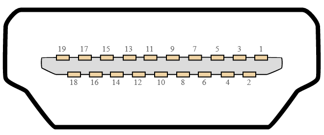
This diagram shows an HDMI socket, if you're poking pins into the cable then flip left to right.
| HDMI Pin Number | Signal |
|---|---|
| 1 | TMDS Date 2+ |
| 2 | TMDS Data 2 shield |
| 3 | TMDS Data 2- |
| 4 | TMDS Data 1+ |
| 5 | TMDS Data 1 shield |
| 6 | TMDS Data 1- |
| 7 | TMDS Data 0+ |
| 8 | TMDS Data 0 shield |
| 9 | TMDS Data 0- |
| 10 | TMDS Clock+ |
| 11 | TMDS Clock shield |
| 12 | TMDS Clock- |
| 13 | CEC |
| 14 | HEC Data- |
| 15 | SCL (Serial Clock for DDC |
| 16 | SDA (Serial Data Line for DDC |
| 17 | DDC / CEC / HEC Ground |
| 18 | +5 V Power (50 mA max) |
| 19 | Hot Plug Detect (1.3) / HEC Data+ (1.4) |
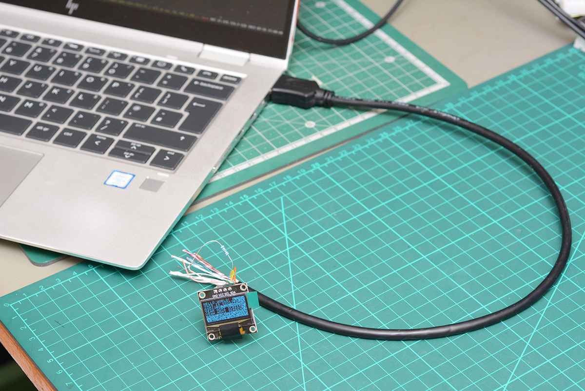
I've a tendency to choose low-risk options when it comes to hardware hacking, no one likes seeing blue smoke, especially if the dev board was expensive. Today though I feel like living on the edge, and I'm going to solder this display directly onto the severed HDMI cable coming out of my reasonably new laptop. What a thrill! If we mess up, this stupid experiment could be very expensive.
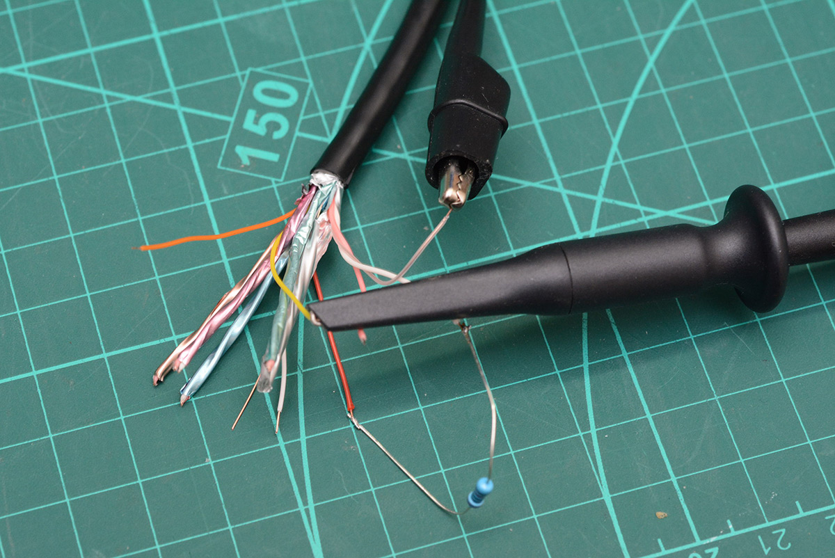
You have to register to download the HDMI spec which is more effort than I have for this, but the Hot Plug Detect pin has a pretty descriptive name. I guessed that this either has to be pulled up or pulled down to signal that a cable is connected. Sticking a 20K resistor to the 5V pin seemed to do the trick. With the oscilloscope, we can now see activity on the SCL/SDA lines when it's plugged into the laptop.
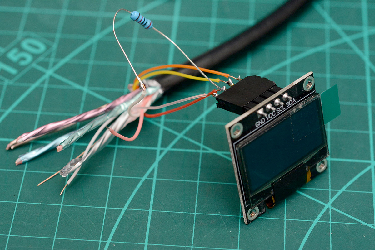
I then boldly soldered a header connector to the four lines we care about. I'd ordered a couple of OLED screens for this experiment, they both use the SSD1306 controller, and come on breakout boards with the four pins on a header.
i2c and SMBus
On linux we can access i2c devices by loading the i2c-dev module (modprobe i2c-dev) which makes a bunch of i2c devices appear at /dev/i2c-*. My laptop shows nine i2c devices.Some of these are in fact SMBus, which is a subset of i2c. As far as we're concerned it's just i2c with a bunch of extra restrictions, such as limiting transactions to 32 bytes.
It's also worth installing the i2c-tools package which comes with the i2cdetect utility and sets a udev rule for group permissions. To access i2c devices without sudo, add yourself to the i2c group (sudo usermod -G i2c -a username) and log in again for it to take effect. I also had to run udevadm trigger for the udev rule to take effect. Might have been simpler to reboot (never!).
Beware: the i2c device naming is not consistent. I figured out that /dev/i2c-3 was the HDMI DDC line I'd soldered to, but after unloading and re-loading the module, it became /dev/i2c-4. We need to be really careful about this, writing (or even reading) to the wrong i2c device could easily muck up some of the laptop hardware.
I installed another package, ddcutil, only to be able to do ddcutil detect. This lists displays and their associated i2c bus. It's also possible to do i2cdetect -l which lists the i2c devices and their description. In my case, three of the i2c lines had "i915 gmbus" in their description, i915 is the intel graphics driver. ddcutil is still probably the easiest way to figure it out.
Initial tests
The scope showed the SCL/SDA lines are already pulled up, so we should be able to connect the screen without any other hardware. The 5V line on an HDMI port can apparently source up to 50mA, so we don't even need a power supply. Neat!
i2cdetect can scan an i2c bus for devices. As expected, without the cable connected, it detected nothing on the bus. But when I connected my severed cable, with the hot plug detect resistor in place, a whole load of responses appeared. I don't know quite what's going on here (does the video hardware expose a bunch of stuff when the cable is connected?) but the important point is that when I connected the display, an extra device showed up at 0x3c.
The quickest way to talk to the display is with a python script. The bundled smbus library lets us get going very quickly.
import smbus

bus = smbus.SMBus(4) # for /dev/i2c-4
i2caddr = 0x3c

bus.write_i2c_block_data(i2caddr, 0, [0xaf] ) # turn display on
There's a bunch of commands we need to send before we can actually display anything, including enabling the charge pump. Note that the SSD1306 datasheet, at least the copy I found, has an appnote appended onto the end of it that explains the initialization process more clearly than the main document (some of the commands are not documented in the main command table). As always, the fastest way to get going is to look at the source code to existing libraries, so I found somebody else's library for the SSD1306 and copied their init commands. The display sprang to life!
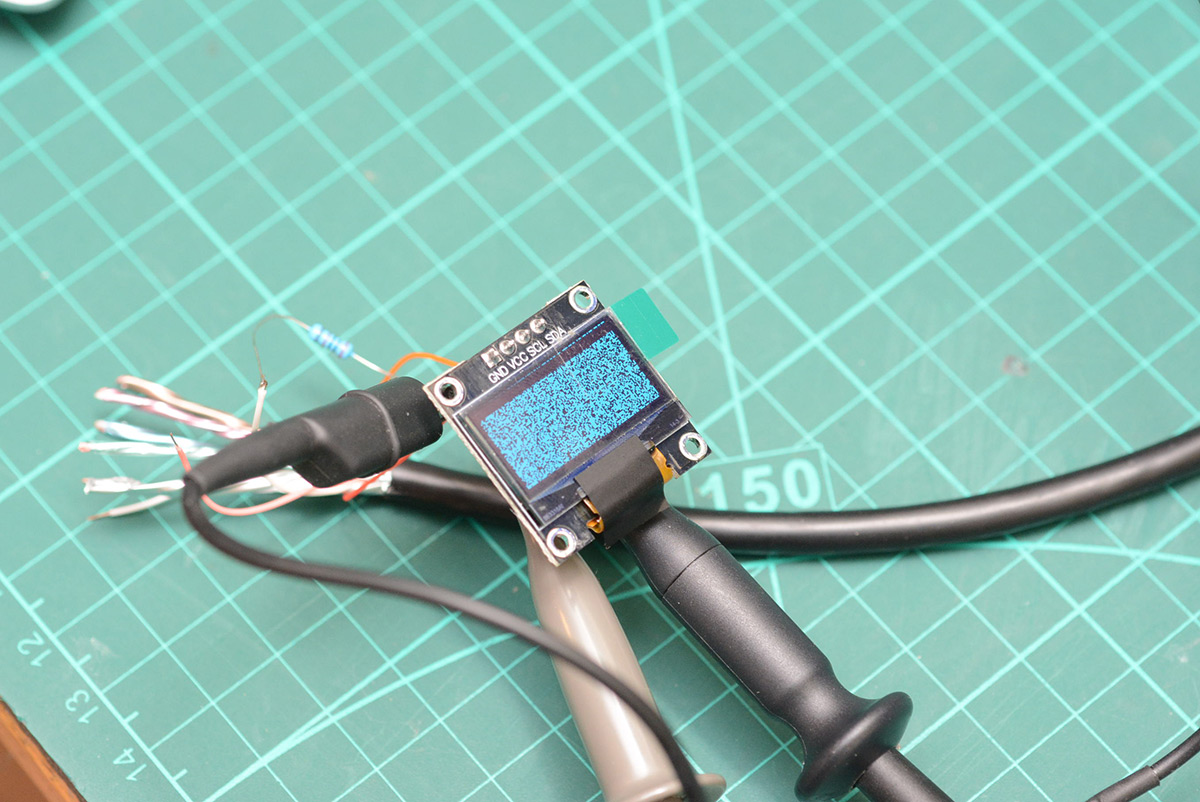
I also found a script to draw text to an SSD1306, and quickly patched in my smbus stuff. Success!
No microcontroller, no other hardware, just an SSD1306 OLED plugged straight into the HDMI port. I find this very satisfying.
Dumping data to it
Sticking with the python script for now, I'd like to be able to take a 128x64 pixel image and dump it onto the display. The text-drawing routine I borrowed uses SSD1306 commands to control the column and page address that data is being written to, so a single character can be drawn without affecting the rest of the display (hence the uninitialized background pixels remaining in that image above).There's a whole load of different memory addressing modes for this thing, along with confusing terminology. SEG or COL is the X coordinate, COM is the Y coordinate, but these are grouped into pages. The datasheet has some diagrams.
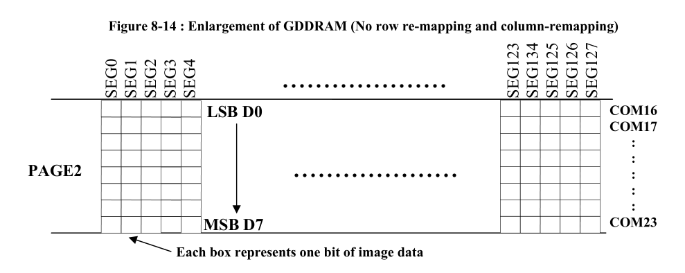
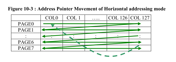
The display is monochrome, each page is 8 rows (COMs) and when we pipe data to the display, each byte is one page, one column of pixels. It may have made more sense to configure the display for vertical addressing mode, so the bits would all be in order, but I figured it would be quickest to just do the bit-shuffling at our end.
With python PIL (pillow) we can convert an image to monochrome with .convert(1) and serialize it with .tobytes(). This will have each byte represent 8 horizontal pixels, but we want each byte to represent 8 vertical pixels. Instead of doing some tedious bitwise logic, the fastest way to fix this is by rotating the image 90 degrees before we serialize it, then loading those bytes into a numpy matrix and transposing it. It's the kind of thing that either works perfectly first time, or outputs a complete mess, in which case you just permute the order of operations until it works. So much easier than thinking.
As I mentioned, SMBus won't let us send more than 32 bytes at a time, even though this device is just plain i2c. We can get around this by accessing the i2c device directly from python. The trick is to use ioctl to configure the slave address. In the kernel header file i2c-dev.h there are definitions for the constants needed, we only care about I2C_SLAVE.
import io, fcntl

dev = "/dev/i2c-4"
I2C_SLAVE=0x0703 # from i2c-dev.h
i2caddr = 0x3c

bus = io.open(dev, "wb", buffering=0)
fcntl.ioctl(bus, I2C_SLAVE, i2caddr)

bus.write(bytearray([0x00, 0xaf]))
By alternately sending 1024 bytes of zero or 0xFF, I could gauge how quickly this updated the display. Seemed to work fastest by sending 256 bytes at a time, not sure if that's a limitation of the i2c hardware (is there some extra layer of buffering?).
With this I could get between 5 and 10 frames per second (compared to about 2FPS with the SMBus limitation). I think the DDC is running at 100kHz, but regardless this is certainly pushing the limits of what it was intended for.
Make it a monitor
We could just write our application to draw directly to this screen, but that's not good enough, I want it to be a monitor.(I'm not sure what our application here even is, but that's beside the point. I want it to be a monitor!)
We could write our own video driver. As educational as this sounds, it would be a colossal amount of work and I was rather hoping to have this wrapped up within the evening.
There are a bunch of dummy video drivers in existence, these are intended for headless machines in order to enable VNC and so on. xserver-xorg-video-dummy may function for us, but I have a terrible feeling this won't play well at all with us also having real display outputs. There's Xvfb, a virtual framebuffer, but this won't do us much good if we want to have our desktop extend onto it.
Since I'm using xorg, it seems the right way to fake a monitor, without spending days on it, is to go through xrandr.
xrandr is both a library, and a userspace commandline utility.
It took me a while to get to grips with the xrandr terminology. It's not particularly well explained.
- The "framebuffer" is the whole desktop, i.e. what gets saved if you take a screenshot.
- An "output" is a physical video output.
- A "monitor" is virtual concept, that normally is mapped to all or part of the framebuffer, and normally corresponds to one output. If you maximize a window, it fills the dimensions of the monitor.
- However, you can have one display output be more than one monitor (for instance, to split a widescreen display into effectively two monitors)
- Or, multiple outputs can be one monitor, i.e. multiple physical screens can be treated as if they were a single display, maximizing a window would cover all of them.
- a "mode" is a video format, consisting of at least width, height and framerate. Specifically, VESA CVT modelines are used, and can be generated with the
cvtutility.- xrandr's addmode and delmode refer to associating an existing mode with a display output
- xrandr's newmode and rmmode refer to adding a new mode to the server, that can then be associated with an output
Note that this list is specific to xrandr, in other aspects of linux, the terms "output", "display", "monitor" and "screen" are often used differently.
On my laptop, calling xrandr shows five video outputs: eDP-1, which is the main screen with a bazillion modes available, and four disconnected (HDMI-1, HDMI-2, DP-1, DP-2), presumably three of which are available via thunderbolt or something.
Faking a monitor, attempt 1
Looking around, it seems the recommended way to do this is to convince xrandr that one of the unused video outputs is connected. For things like VNC there's a whole market for "dummy plugs" which make a video card think a monitor is connected. We obviously don't want or need to do that, we should be able to coax xrandr into behaving through software.In order to output our abnormally low resolution of 128x64 on HDMI, in theory we first generate a CVT modeline:
$ cvt 128 64
# 128x64 39.06 Hz (CVT) hsync: 3.12 kHz; pclk: 0.50 MHz
Modeline "128x64_60.00"    0.50  128 136 144 160  64 67 77 80 -hsync +vsync
then we add this mode to the x server:
$ xrandr --newmode "128x64_60.00" 0.50 128 136 144 160 64 67 77 80 -hsync +vsync
At this point, xrandr shows the unused mode at the end of its output. Confusingly it looks like the mode is part of the last output listed, but it isn't (yet). We next add this mode to one of the outputs:
xrandr --addmode HDMI-1 128x64_60.00
and finally try to use it:
xrandr --output HDMI-1 --mode 128x64_60.00 --right-of eDP-1
I should point out, I've a hotkey on my laptop which cycles through sane display modes, so I'm comfortable trying whatever here, but otherwise there's a chance you end up unable to see anything. It should still be possible to access the other virtual terminals with ctrl+alt+F2 etc, since these configure the display using KMS (Kernel Mode Setting) that sits a layer below the X server.
I tried this with both HDMI-1 and HDMI-2. Both of them are listed as disconnected. Our cable connected to HDMI-1 is pulling the Hot Plug Detect pin high, but not responding to regular DDC queries.
I may not have exhausted all possibilities, but I couldn't get this to work. I suspect the video driver simply can't cope with this ludicrously nonstandard resolution, and the modeline is just junk. The 39.06Hz certainly raised one of my eyebrows. I tried again specifically setting the framerate to 39.06Hz also, to no avail.
Honestly, abusing the video outputs like this feels like a poor solution anyway.
To clean up this mess, first use --delmode to free up the modes from any outputs, then --rmmode to remove them from the X server.
Faking a monitor, attempt 2
When you change display settings xrandr generally sets all the relevant settings automatically, but if we go deeper we can manually fiddle with them. Following another idea on the internet, we should be able to make a virtual monitor by simply extending the framebuffer, and defining a monitor to be there, without bothering to associate it with an output.
Interestingly, if you make the framebuffer bigger than needed, by default it will automatically pan when your mouse approaches the border. Useful to know, but here we need to specifically stop that happening. The --panning option takes up to twelve parameters, for panning area, tracking area, and border. Tracking is the area our mouse cursor is limited to. Normally, panning, tracking and framebuffer are all set to the same size. I'm not sure what "border" represents in the context of panning, it didn't seem to have any effect when I played with it.
Setting panning to 0x0 will disable it, but that also limits the tracking area, so our mouse won't be able to reach the new bit of framebuffer. Instead we limit panning to the size of the main monitor, effectively disabling it, and extend the tracking area into our new chunk of framebuffer. The full command:
xrandr --fb 2048x1080 --output eDP-1 --panning 1920x1080/2048x1080
Then we can define a new monitor to exist in this new chunk of framebuffer:
xrandr --setmonitor virtual 128/22x64/11+1920+0 none
The size is set in both pixels and mm, I guessed it's approximately 22m by 11mm, it doesn't really matter though. "virtual" is the name of this monitor, we could call it anything. "none" is the output. We can see monitors with xrandr --listmonitors and later undo this muck with xrandr --delmonitor virtual.
I can now point my script to dump that bit of framebuffer onto the OLED screen. Hurrah! One slight issue with this method is that the tracking is not L-shaped, my mouse can access the strip of framebuffer that doesn't correspond to any monitor. I don't know if there's an easy fix for this, but if it really bothered us we could enforce valid cursor positions through Xlib in our script.
Reading the framebuffer
I assumed I'd need to throw away the python script at this point but there'spython-xlib which gives us access to most of what we need. It's a little irritating that there isn't really any documentation, and the method names are not identical, for instance XGetImage is now root.get_image.Here is some trivia: did you know that the mouse cursor is rendered by hardware? It makes sense, I suppose. It also explains why the mouse cursor isn't normally captured when you take a screenshot. But we want to capture the framebuffer and the mouse on top of it so there's a lot more work involved.
Getting the cursor image would normally be achieved through XFixesCursorImage but python-xlib hasn't yet implemented all of XFixes. I was prepared to start over in C until I spotted someone's done all the work for me with this repo which binds to X11/XFixes using ctypes specifically to get the cursor information.
We now have everything we need to capture the new virtual monitor image, superimpose the cursor in the right place (remembering to adjust for xhot and yhot, the pointer/cursor image offset), convert the result to a monochrome image with the right amount of bit-shuffling and pipe it to the display continuously.
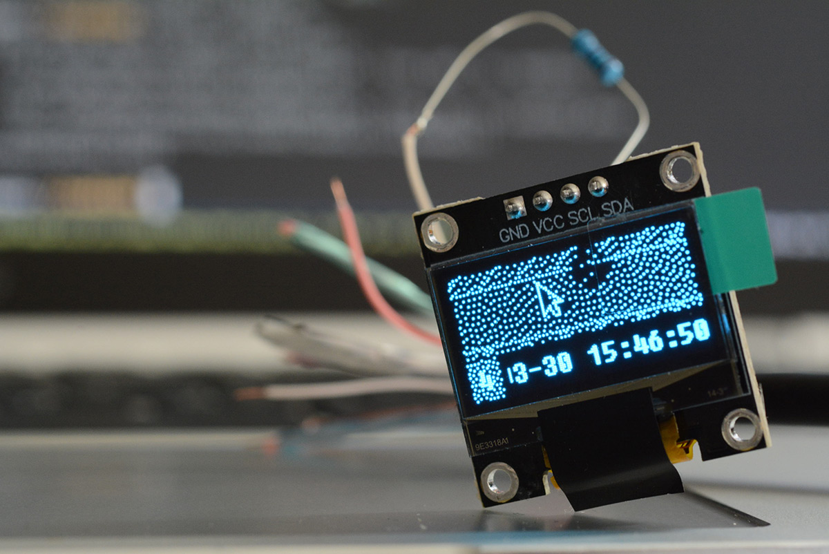
That's i3 workspace four, with a completely crushed i3status and incomprehensible dithered top corner of my background image. Beautiful!
Demo
Conclusion
To improve the framerate, we could enhance our script and only send the changes instead of redrawing the display each frame. As fantastic as this could be, given that I have absolutely no use for this tiny second screen anyway, I'm not particularly inclined to make it happen.If for some mad reason you want to try this out yourself, the script can be found on github.
Update: How can we make the smallest and worst "HDMI" display even sillier? Make it steampunk.