
Games Console Assemblage
22 Dec 2018Progress: Complete
* * *
Kapton tape is key to a project like this. That's my philosophy, anyway. Cover everything in kapton tape and it can't go wrong. With that taken care of, it's time to take the plunge and start cramming it all in.
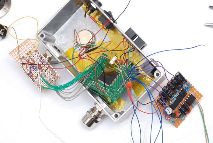
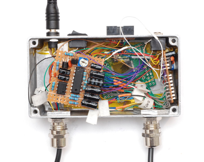
So the ISP connector is glued in place, then we've got the 5V power coming from the barrel jack, no regulator, all straight forward. Video board on the left and audio/power supply board on the right. You'll notice I've added even more capacitance and, to the max232 chip, some resistors. My theory with it is that there are supposed to be internal pullups/pulldowns on the input pins, but for some reason they're omitted. These free floating inputs (it's CMOS logic after all, I think) are the cause of my chip-heating woes. When it's working normally the chip gives off no heat at all. Well, we'll see if that's solved the problem sooner or later.
The video out is connected to a separate 3.5mm jack, that was for testing the effect of different cables. I was thinking about cable impedance and signal propagation, and was reading up on series termination when I found a different cable. It's still 3.5mm stereo to phono connectors, but it has yellow and white on the plugs. This suggests it's intended for video and I think it came from a video camera. Regardless, it works a bazillion times better than the other cables and there seems to be no reason to worry about image quality with it.
Now before we go further, we need to solder the cartridge connector to the board, and re-solder the controllers having threaded them through the cable glands.
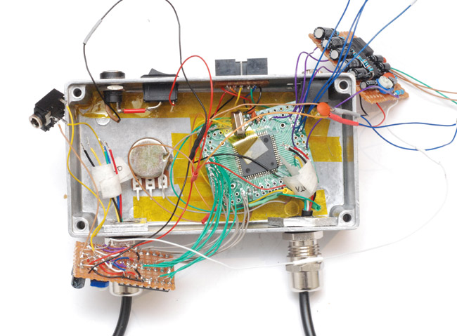
Now we're thinking about how to arrange the insides. Having folded all those capacitors flat, it looks like that'll be going directly over the main board anyway where there's plenty of headroom. We want to minimize the video signal path, so having that close to the connector is good. Can we fit it on the side there? Of course, just my luck, the only capacitors I didn't fold flat are the ones that matter.
I think we can get away with it though. Now for some more bodging.
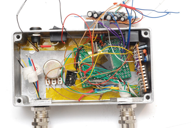
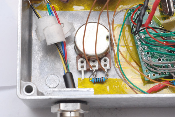
That brown lead with the flying trimpot, that's the main volume control and I nearly forgot that needs wiring to the big pot on the front. Wouldn't want that to end up just decorational now, would we? I pulled the old trick of wiring another resistor in parallel so as to give it a sort-of logarithmic curve.
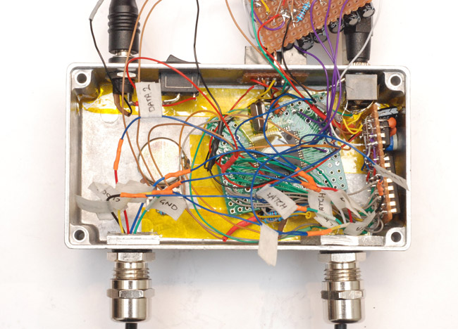
Right, now the only thing left to do is start soldering together the twenty or so loose wires with bits of masking tape on them. And heatshrink everything to avoid shorts. It's all blue/orange because I'm lazy and at this point if we make a mistake I don't think coloured wires are going to be any help.
The tension is building now. Are you as excited as I am?
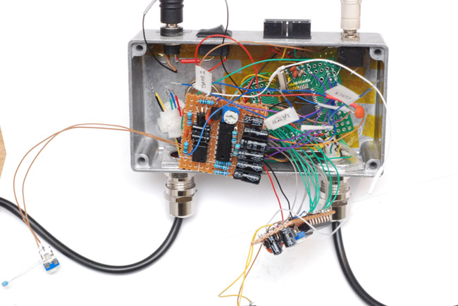
And the lid goes on. That, too, got the kapton tape treatment. More screws to insert.
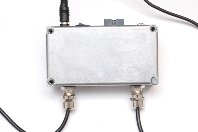
Now to tighten those cable glands.
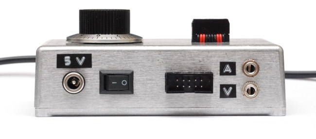
And let's not forget the labels. Very important, these labels. How else would you know what voltage it needs, and which of the two jacks are audio or video?
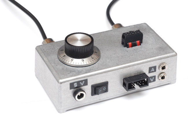
Maybe label the volume knob? Cartridge connector? ISP port? You know there's an old saying, "When all you have is an embossing label maker, everything looks like a labelable surface" errr...nevermind.
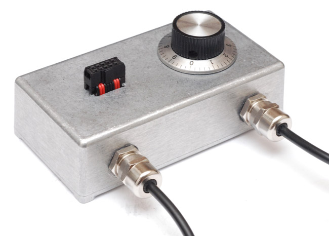
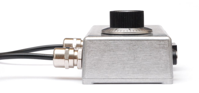
Now, for some vanity shots.
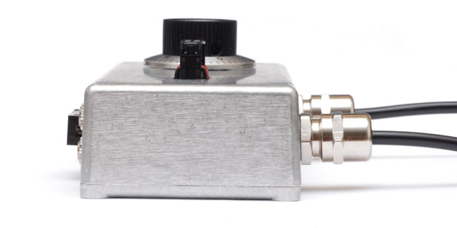
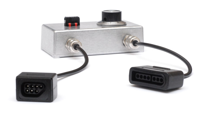
Oh and yes, having taken these shots, I decided to add more labels.
Enough hardware. You're probably dying to see it working. (2018 edit: Well, not if you've already watched the video, but I bet you're desperate to dive deeper into the assembly source code, right?)