
POV Candle
1 Dec 2023Progress: Completed
A tiny volumetric display!
Video Demo
Naturally you can't really feel the volumetric effect on camera. It looks a lot more 3D in real life.
Idea
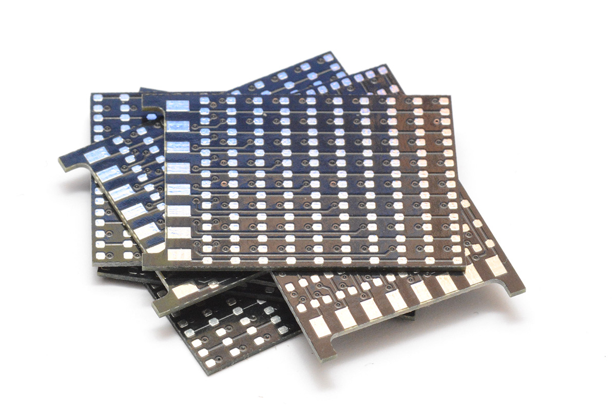
I was recently fortunate enough to find myself in the pub with some very creative and talented people. The discussion turned to electronic candles, and how one might create something that would look like a flickering candle from any angle. I suggested a persistence-of-vision display, but the general consensus was that those require too much in the way of supporting machinery to make them work: bearings, and probably slip rings and so on.Afterwards I had a think and figured that if the motor and battery were small enough, the whole thing could spin. I was ordering some other circuit boards the following day, so I quickly threw together a simple LED matrix board and combined that with the other orders. Small circuit boards from China are essentially free, fast postage is the only thing that matters.
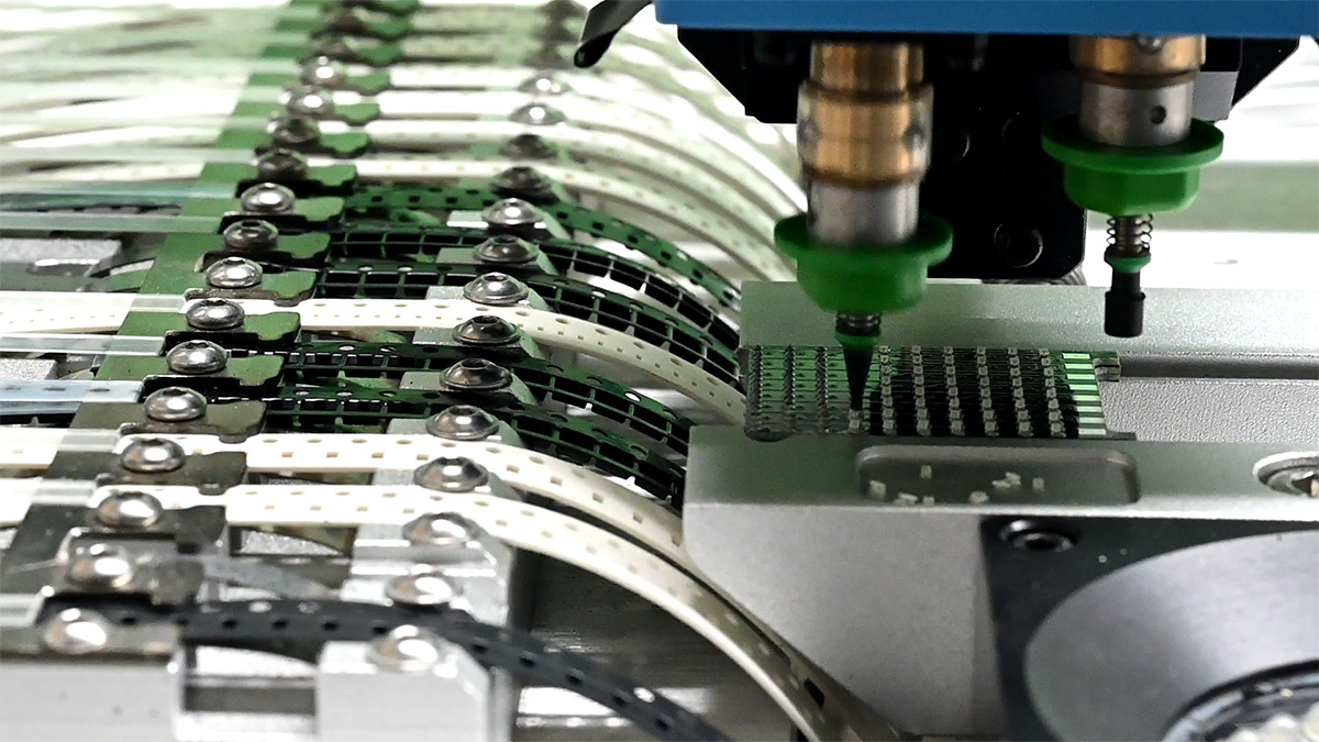
Some time ago, I got access to a pick and place machine (a Charmhigh CHM-T36VA). I have it on semi-permanent loan. It's specifically for another project, which I will write up eventually, but my feelings on it can be summarised as follows: Robots are the Future. I've spent enough of my life manually assembling circuit boards that to have a machine that can build a board in seconds right in front of me is bliss.
The one drawback to it is that loading the reels takes a long time. For each unique component you have to tediously load the reel, which can sometimes take the best part of 20 minutes. The circuit I borrowed the machine for has 26 unique components, so loading the reels was a full day of work.
However. This LED matrix has precisely one component, and so loading the reels was as short as technically possible. Then we can crank out the boards at break-neck speed!
I didn't get a proper stencil, I just laser-etched one in acetate. This project was still very much at the minimal-investment stage, where I'm just idly throwing ideas around. But a generic tiny LED matrix seemed like a worthwhile thing to have a handful of, it will almost certainly come in handy.
I did some with 0603 and also some with 0805, as I had some of those already loaded.
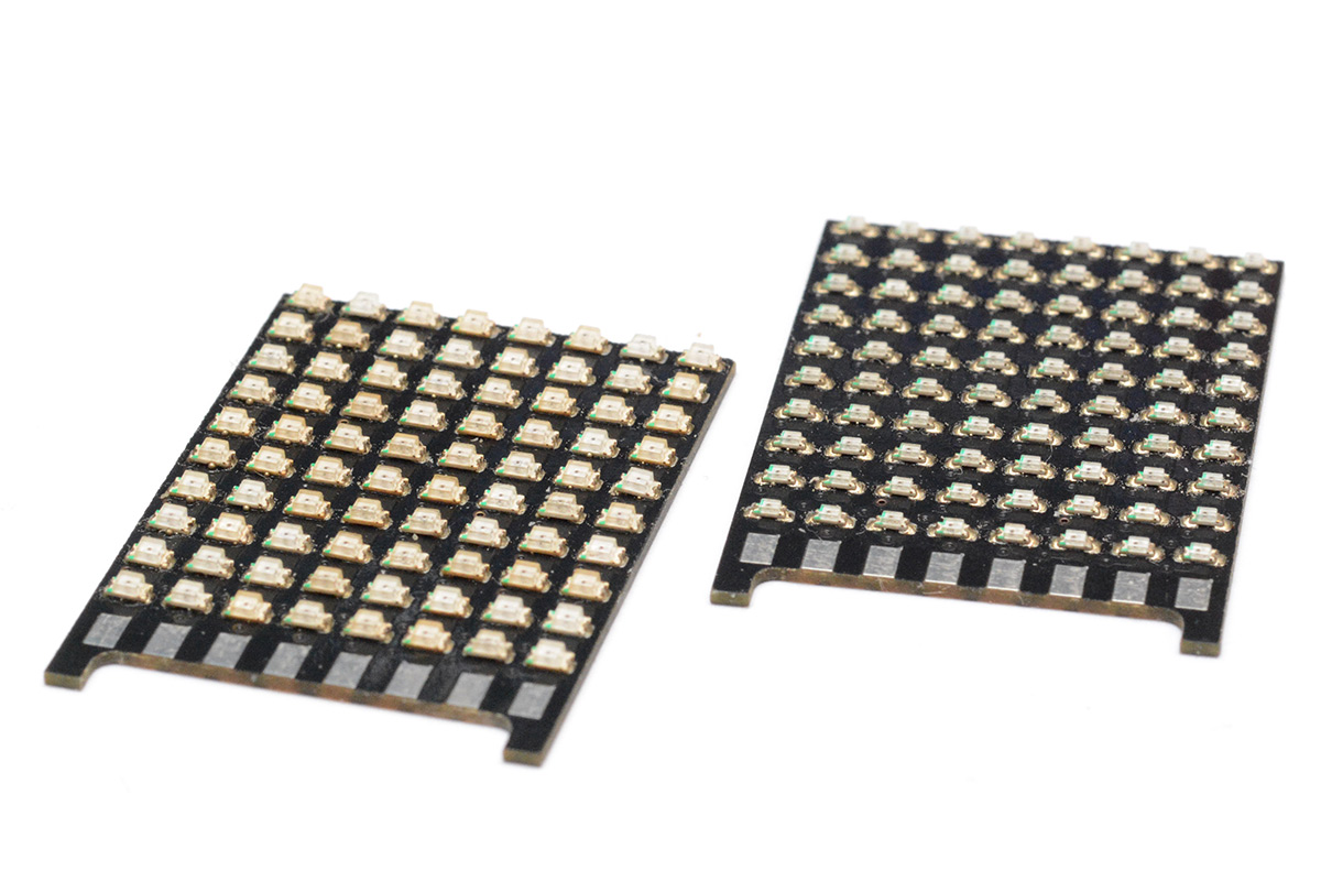
If the circuit board design hadn't been a rush job, I'd have also made a circular PCB to support it at a right angle. The pads along the bottom were to solder directly between the boards. When I come to building the next version, that's what I'll do.
For now I was playing with ideas. I knew that I wanted a microcontroller with a fair bit of flash memory on it, as we may want a fair bit of volumetric video data. The temptation was to go with a Pico, that's dual core 125MHz (or more) and up to 16MB flash (and importantly, it's cheap). One of the main drawbacks to the Pico is that it's a pain to use the bare RP2040 chip on its own. It has no onboard flash memory, so at the very least you need to wire up a QSPI flash chip, and almost always you'll need an external crystal and a fair amount of supporting caps. The Pico board on its own is far too large for our situation.
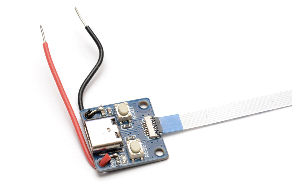
However, a bunch of people have produced minimal RP2040 boards catering to exactly this sort of situation. Most of them were inappropriate, either too big or not breaking out enough of the GPIO. I found one that looks promising called the Waveshare RP2040-tiny. Here they've essentially cut the pico board in half, putting the bare minimum on the main board and having a secondary board, connected by a flat flex cable, with the USB port, reset and boot buttons.
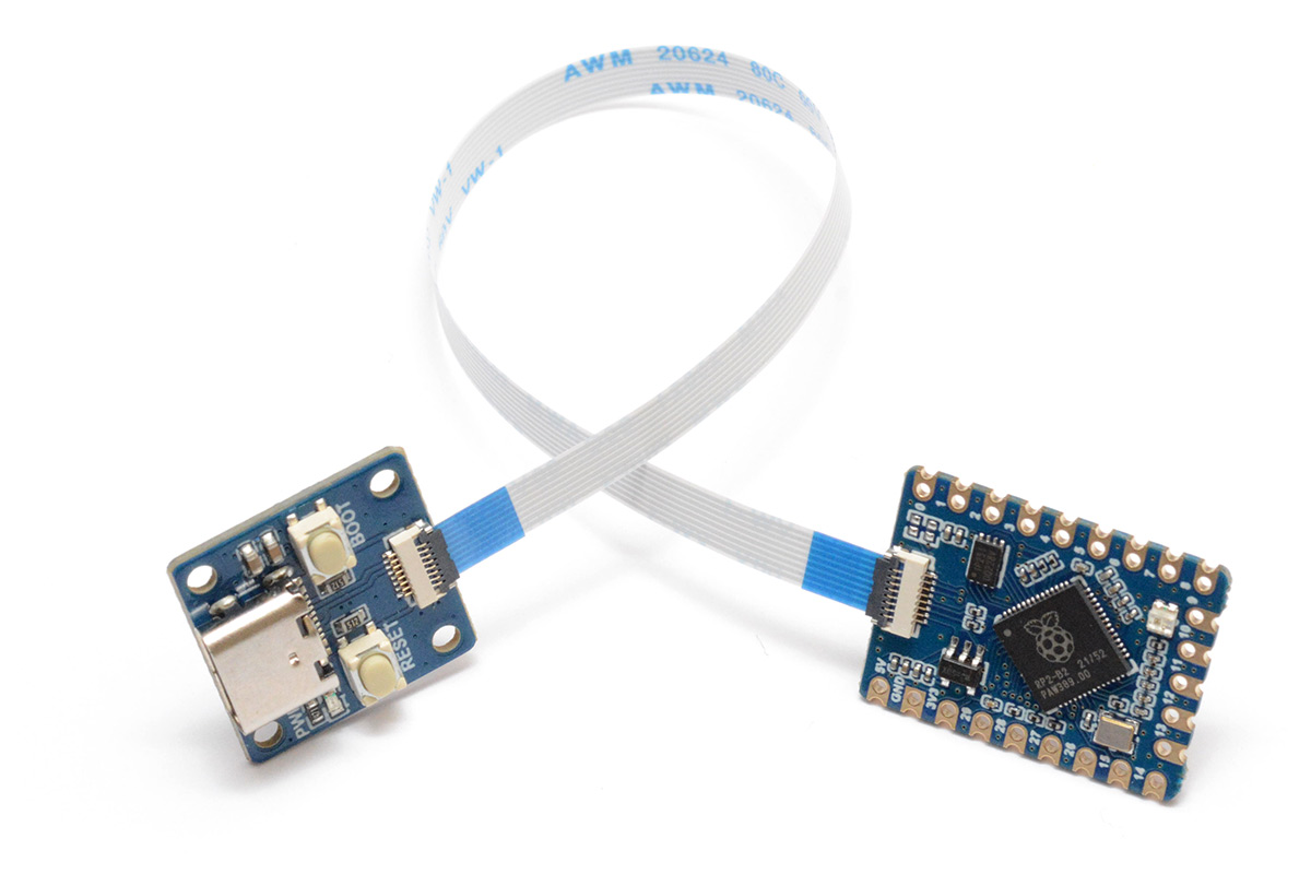
This seemed perfect for our prototype. It's still a little too big, and still doesn't break out all the GPIO, but we should be able to get by.
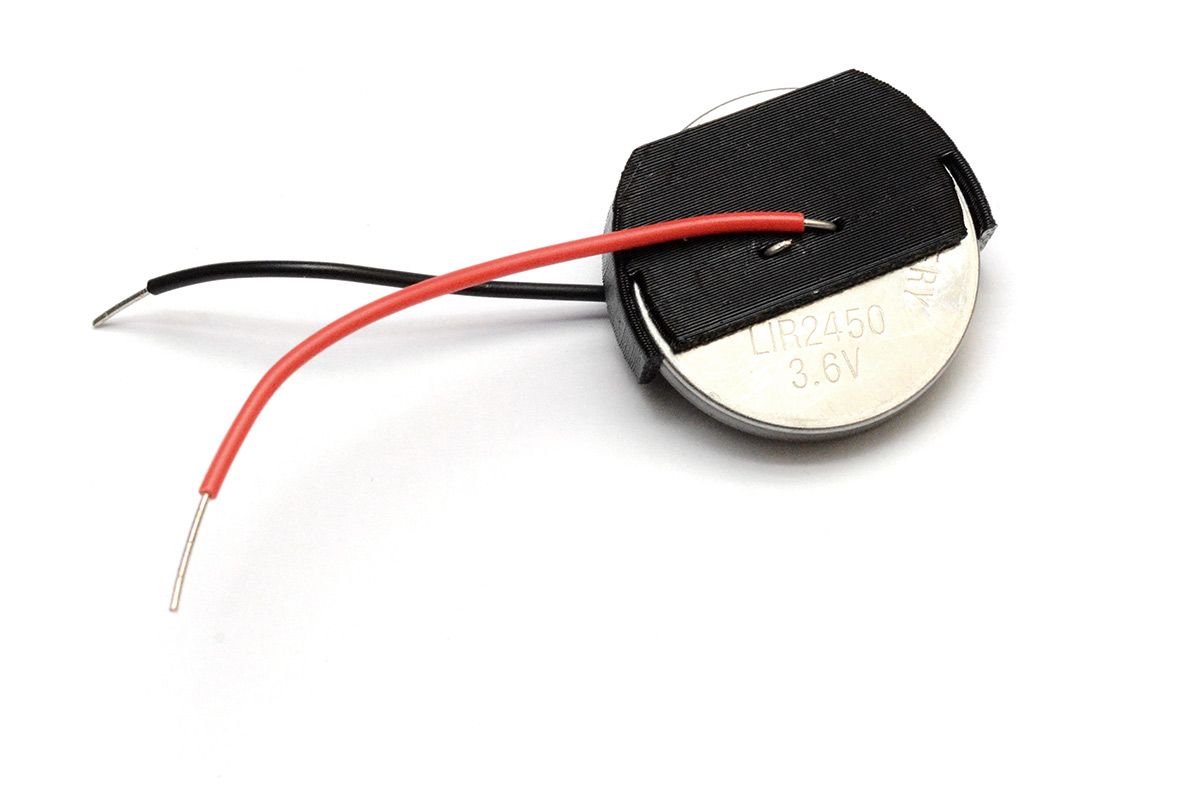
As for the battery, I immediately grabbed a LIR2450. It's lithium-ion rechargeable, and can deliver well over 100mA. You can get smaller Li-ion batteries, but their capacity and current capability are much reduced. I also get a bit nervous having LIR2032 batteries lying around, as I feel like I'm going to accidently put one into something expecting a CR2032 (same physical dimensions) and possibly break it (LIR batteries are 4.2V fully charged). And besides, that RP2040 board is about 29mm diagonally, so going with a smaller battery isn't going to make the end result any smaller.
I 3D-printed the most minimal holder for the battery in PETG.
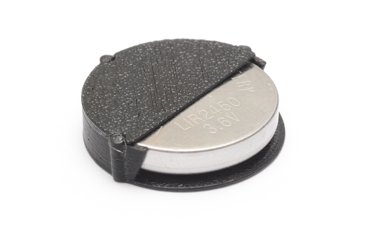
I was definitely too frugal here, printing with a wall thickness of 0.5mm. It's printed in two parts, with the top glued on. I think it would make more sense to thicken up all of the parts and print in one go at 90 degrees, which is something I played with later. This 3D printed part is definitely the weakpoint, every time I drop the prototype it breaks and I have to glue it back together.
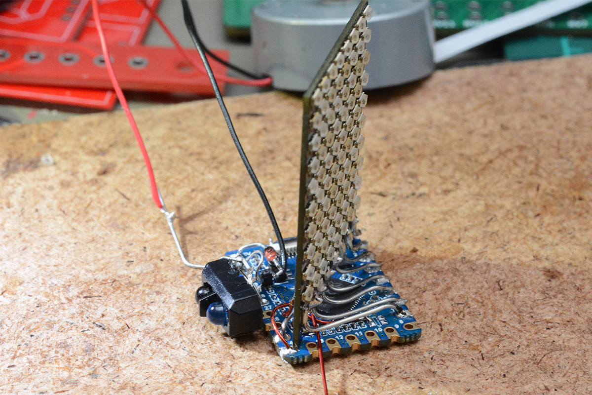
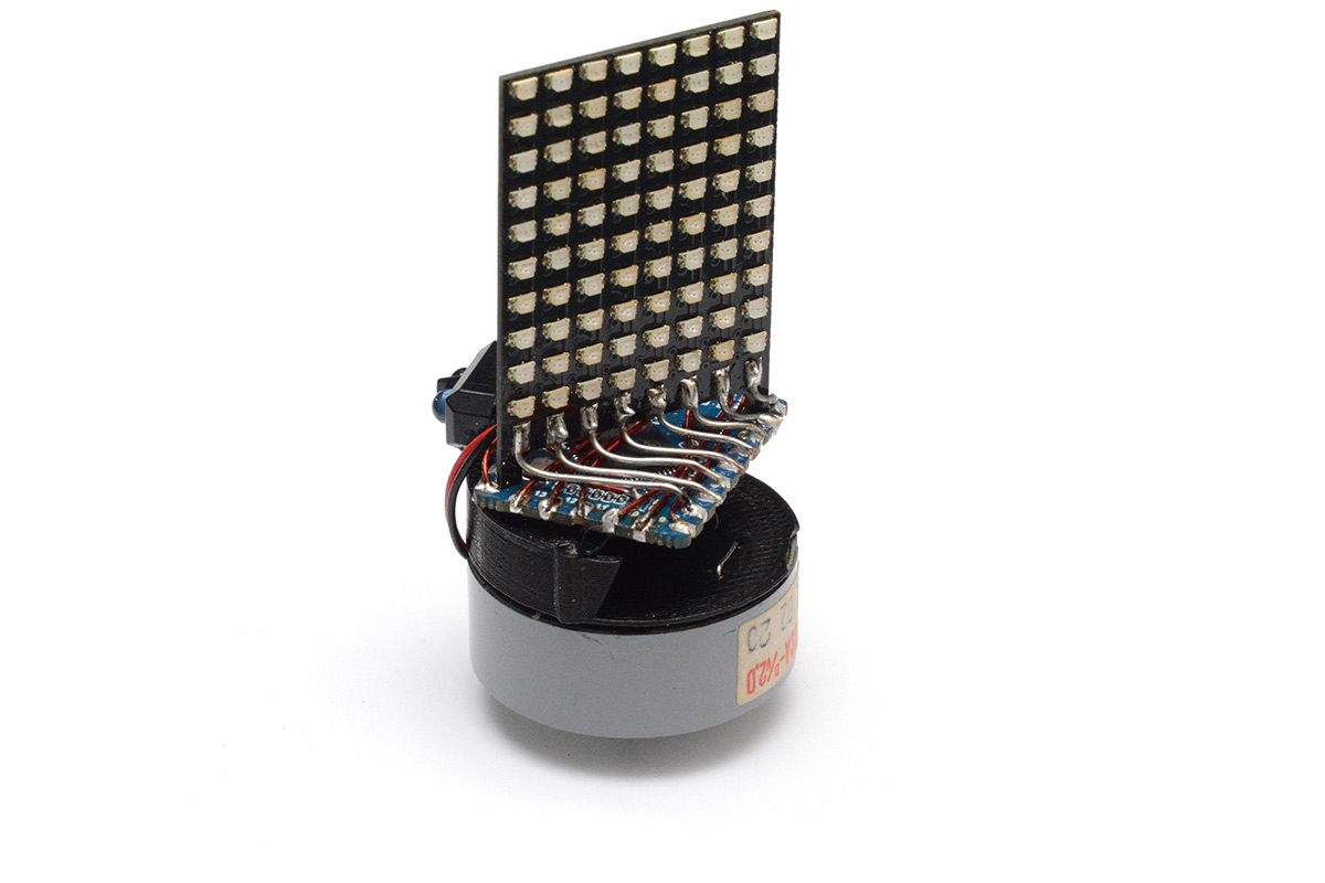
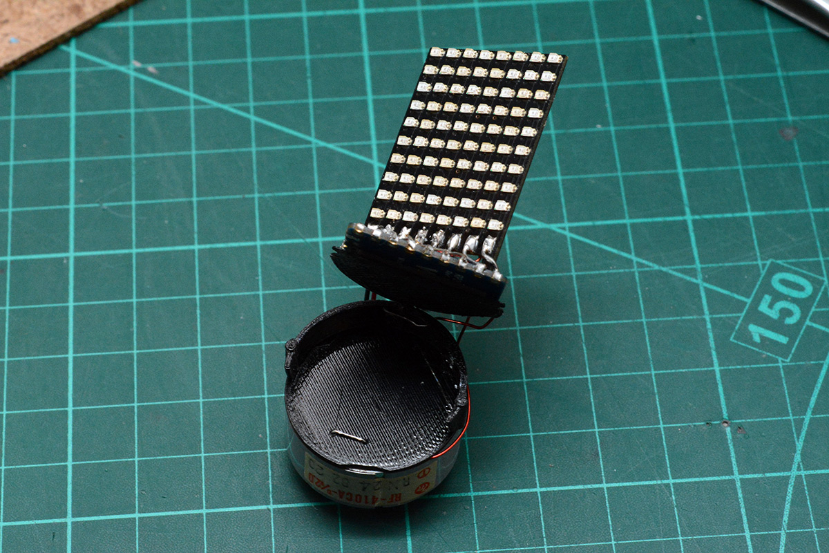
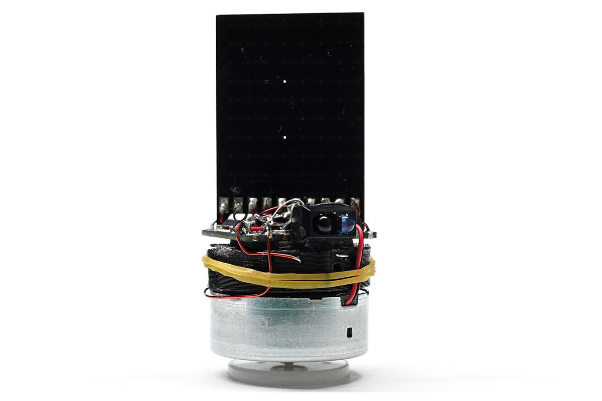
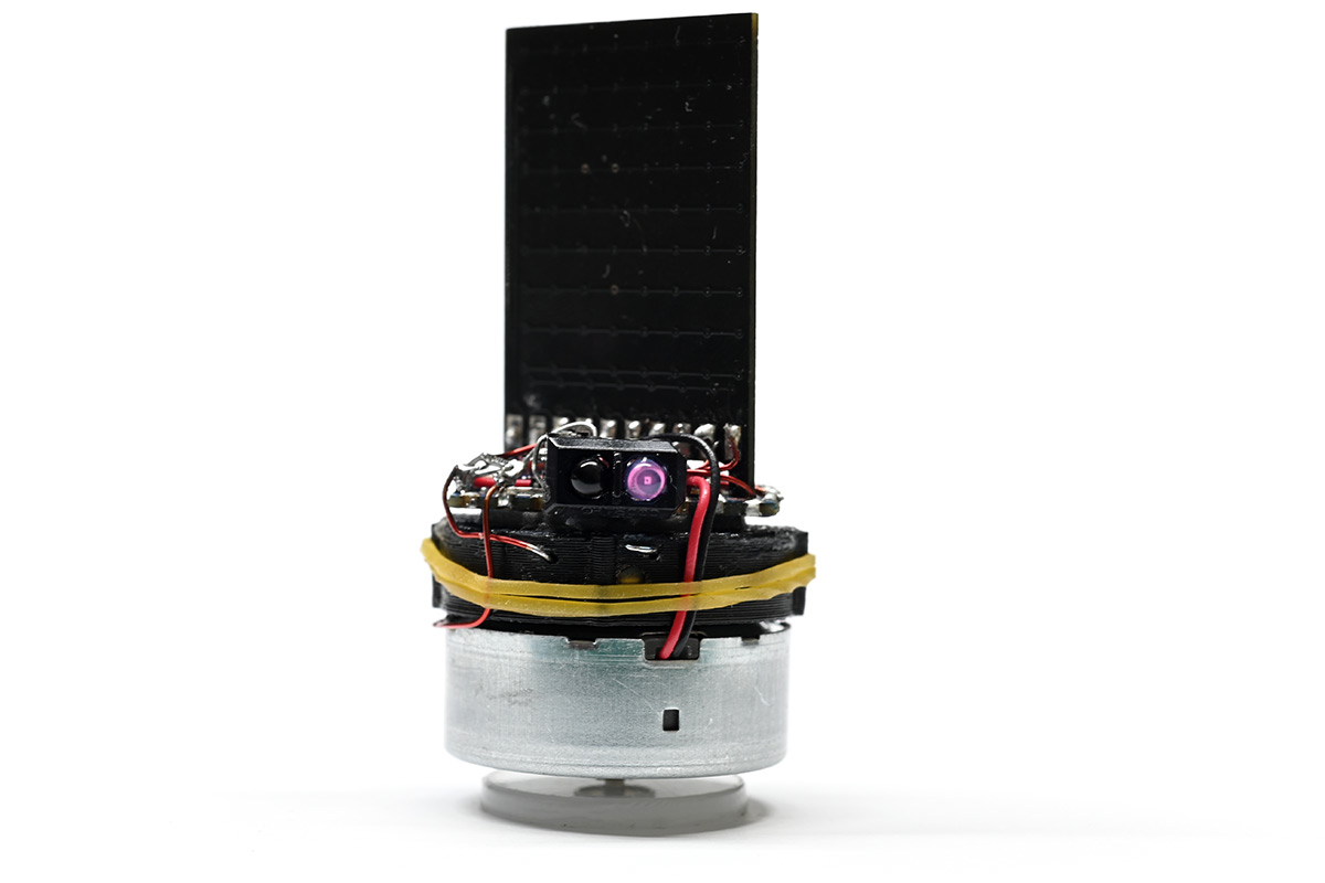
Anyway, we got as far as our first mockup:
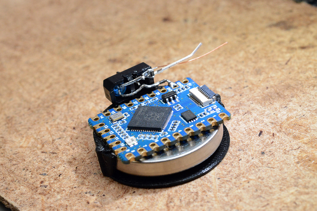
That's a TCRT5000 IR sensor I've soldered on, with tiny surface mount resistors. The sensor is a little on the big side but it's all I had to hand. The output is analog, the detector is just a photodiode, but we can use a pullup and connect this straight to a GPIO pin. There are schmitt triggers on the inputs of the RP2040 (that can be disabled through software) so we essentially get a comparator for free.
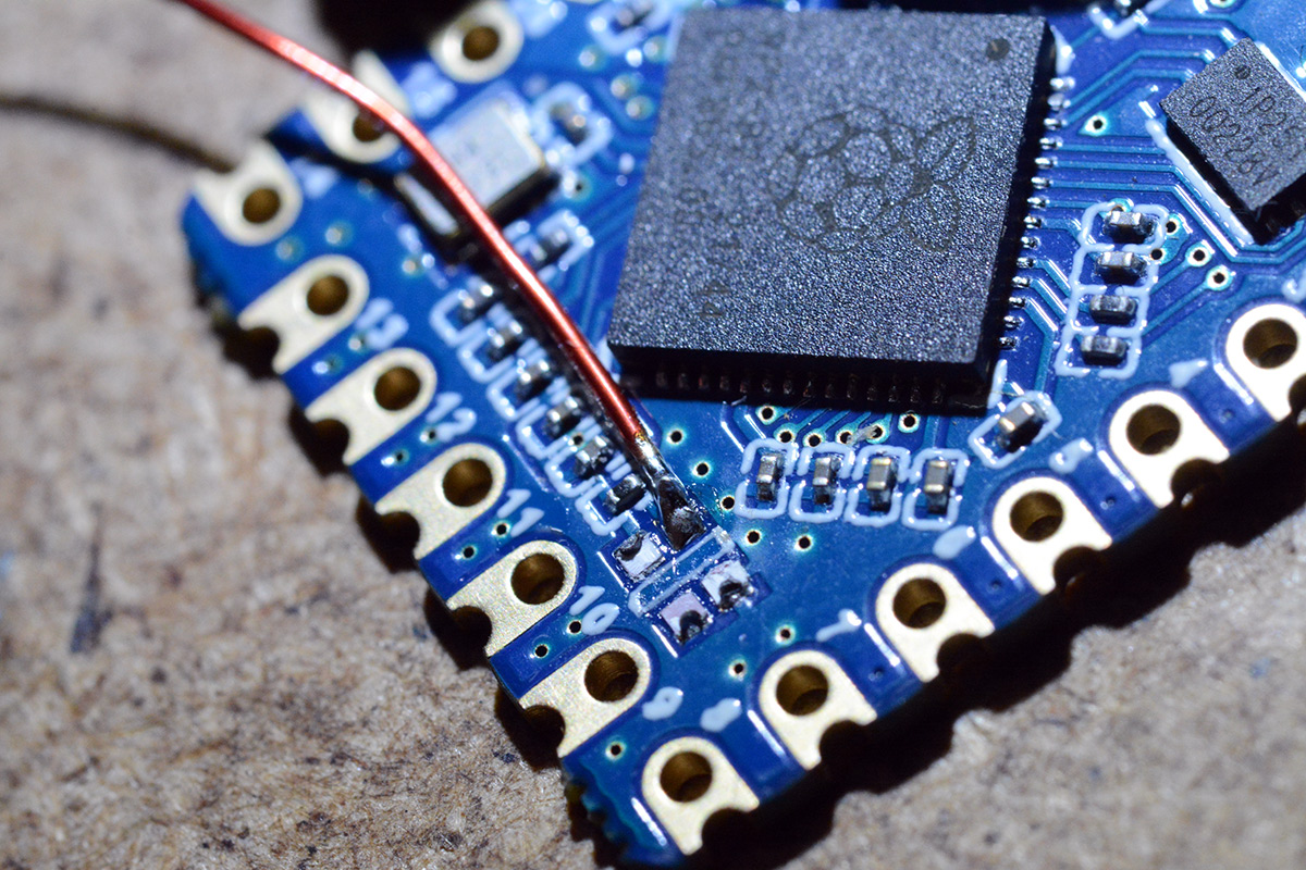
There's a WS2812 LED on the board, connected to GPIO16. I would much rather just have an extra GPIO pin for my matrix, so I snapped off the LED and soldered some enamel wire to it. I wasn't sure if it would be needed but now is the only chance we have to do this.
I then started soldering our matrix. The idea with the tabs at the bottom of the matrix was to have slots in the board I connect it to, which would keep everything aligned. Instead, it seems they work well as little legs to keep the board just above the components. I soldered solid-core wire to the pads and wired it up so that everything would be very rigid at the end. It's possible to correct the angle between the boards, but it takes enough force that it won't happen by accident.
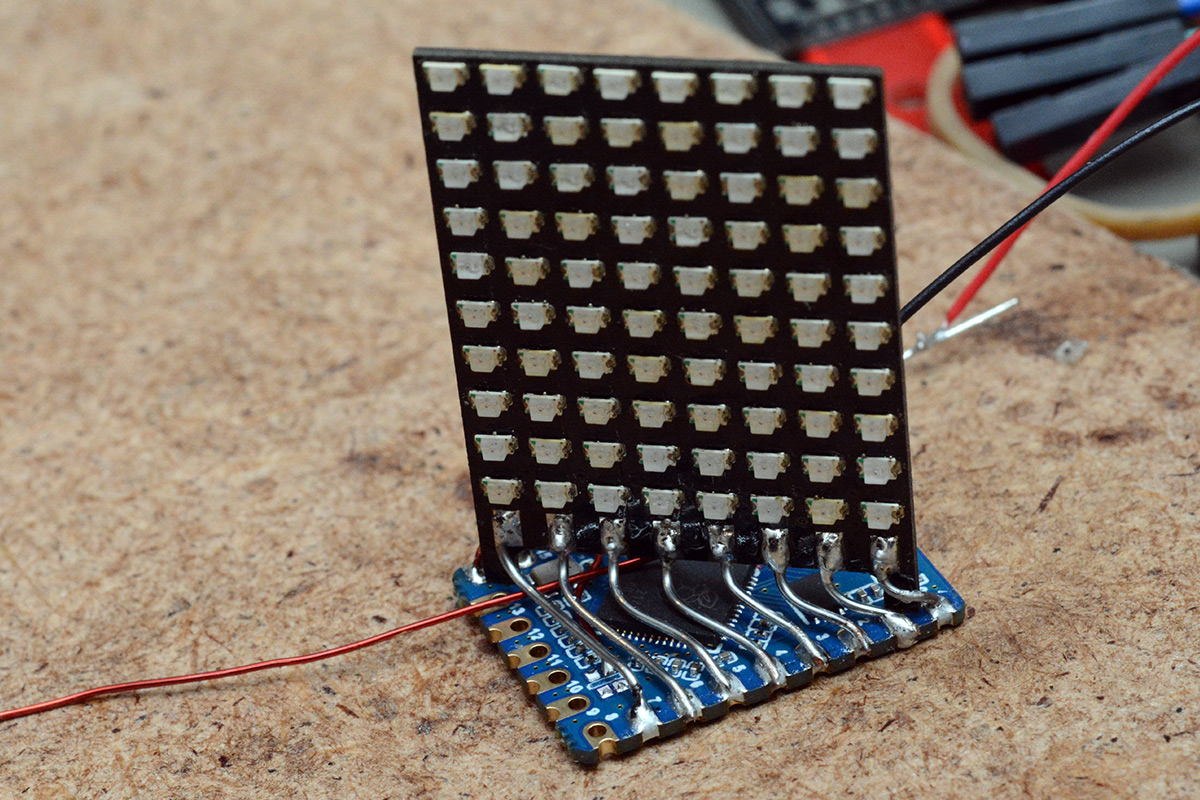
That's half the connections done, there's another ten wires to solder on the back, but before we do that I wanted to wire up the motor.
I have a handful of motors approximately the right size. The one I opted for is labelled RF-410CA. Most of the similar motors from CD and DVD drives are all slightly different diameters and different shaft lengths. I also had a think about RPM. Most of these motors have a no-load speed of 5000 to 10000RPM, which is far too fast. We can PWM the speed down, but it also says something about their starting torque. To get to 30FPS, I'd need an RPM of 1800. It's quite hard to make decisions here, because as soon as it starts spinning there will be air-resistance and it will probably hit some equilibrium. Eh, if the motor's no good we can switch it out later.
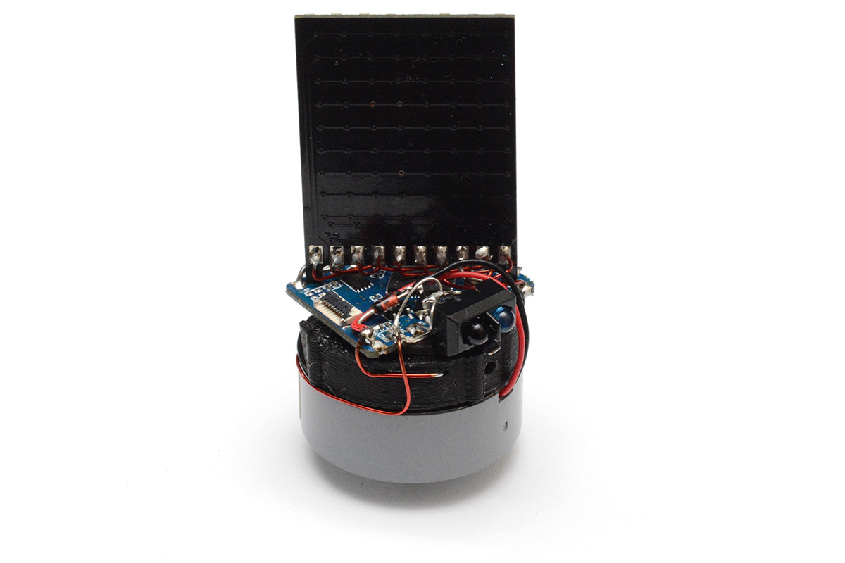
I deadbugged a little sot-23 mosfet and a flyback diode onto our creation.
The IR LED was wired straight to the power line. Ideally we'd have software control over it to save power while it isn't spinning, but for this prototype I didn't want to waste a GPIO on that. The matrix is 8x10, so 18 GPIO, plus one for the sensor input and one for the motor control, and I also wanted to keep one for monitoring the battery voltage. I think it's possible to wire up a couple more of the GPIO on the RP2040-tiny board which have been broken out as "user mode selection pads" but the current thought process was to not worry and get this to a working prototype as quick as possible.
Notice I'm wiring the matrix directly to the GPIO pins. There's no current limiting or driver transistors. The RP2040 can source/sink about 50mA total across all its GPIO. I have learned that the risky, but oh-so-appealing way to drive LEDs from microcontrollers is to skip the current limiting resistors and drive them with PWM. The inherent on-resistance of the GPIO pin is enough to limit current – maybe not to a safe level for continuous illumination, but predictably. As long as you limit the duty cycle it's fine. Here we'll be flickering all of the matrix very quickly, with a lot of careful timing around it. I think it's unlikely we'll overdrive an LED, unless the chip crashes and the matrix freezes.
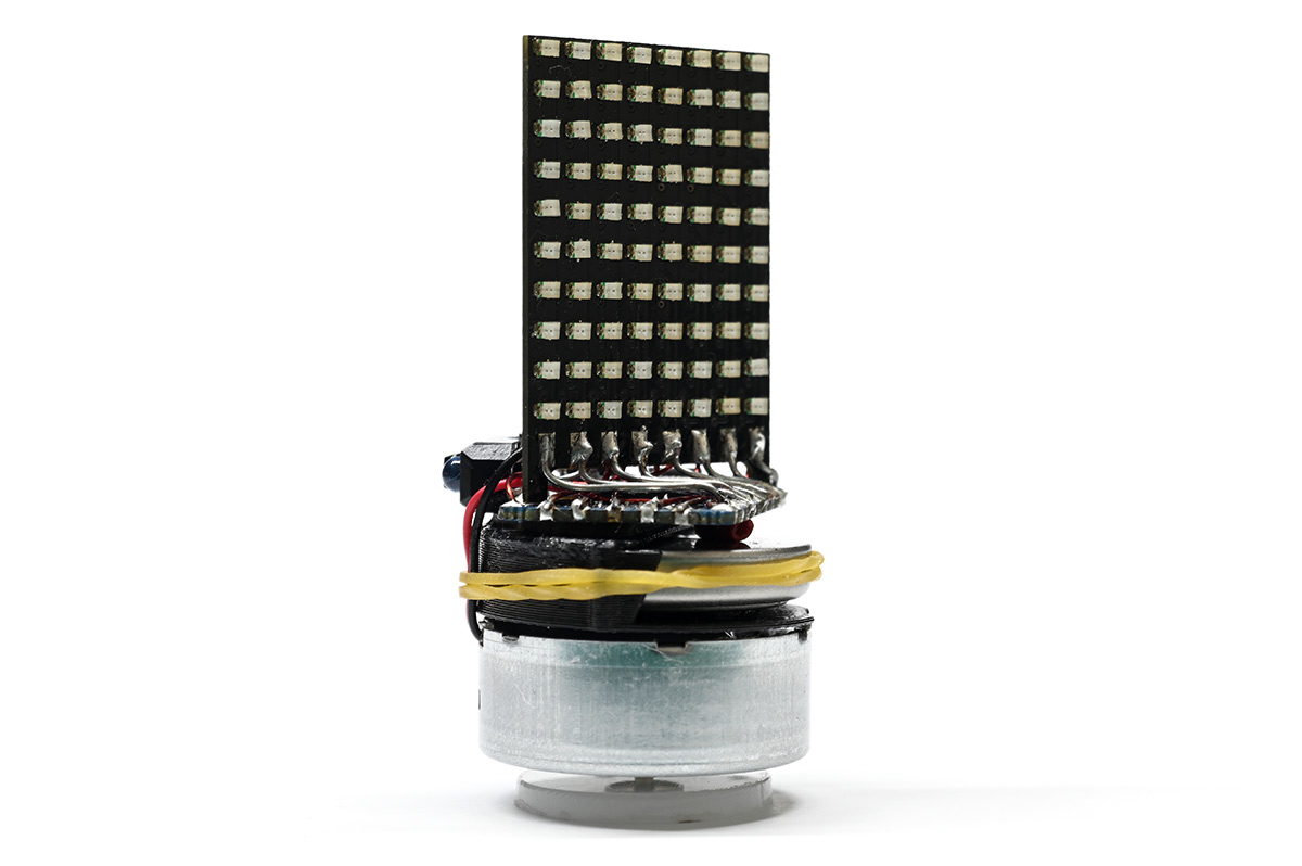
I wired up the rest of the matrix using enamel wire, threading it underneath. We didn't need any further rigidity and it looks pretty cool this way.
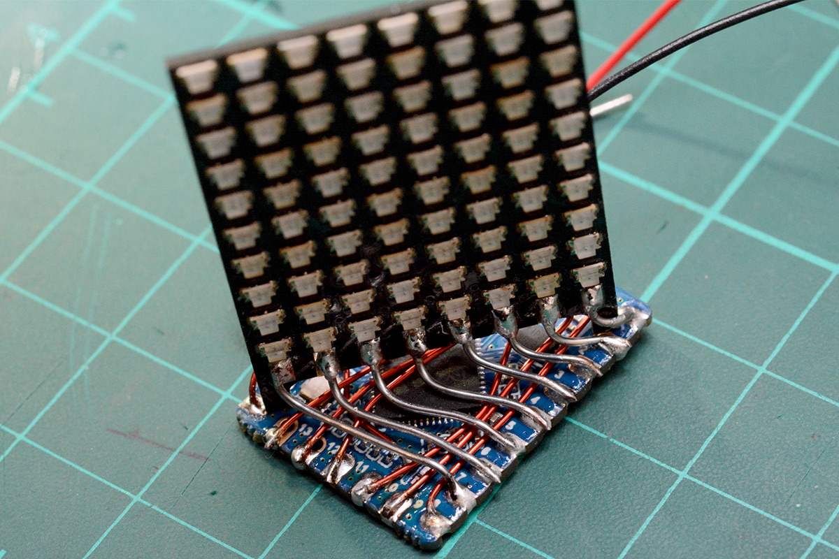
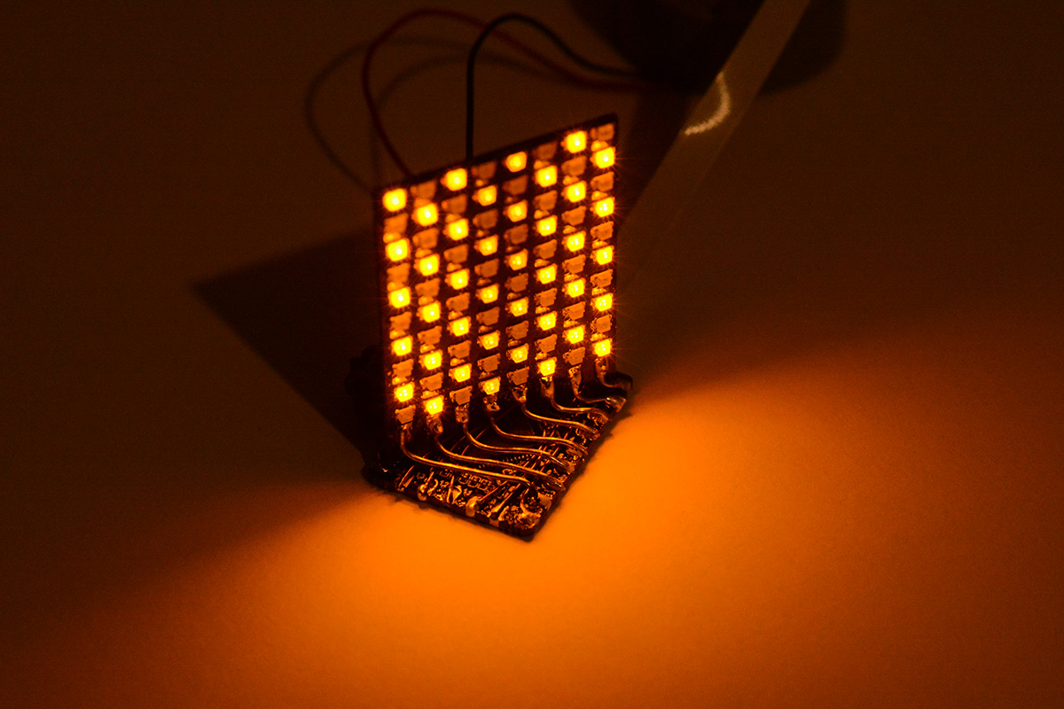
There is something surprisingly appealing about the naked wires. It has a kind of cyberpunk vibe. The vibe was only enhanced when I powered up the matrix with a checkerboard test pattern for the first time.
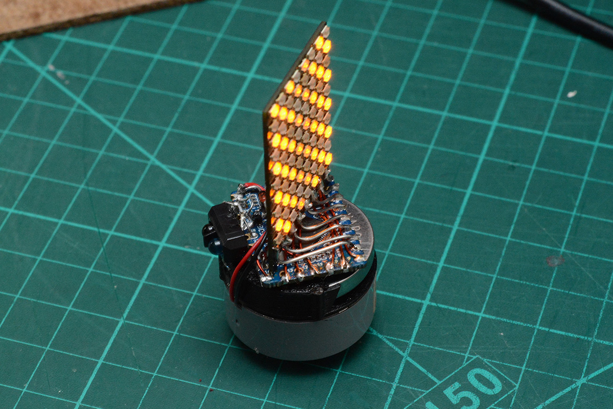
I glued our 3D printed battery holder onto the motor, and attached the rest of the prototype with squidgy 3M tape. I then had to shorten the wires to the motor and connect up the battery terminals.
I wired the battery's positive terminal straight to VBUS of the board. The RP2040 is behind the 3.3V regulator, but with the battery connected this means that connecting the USB cable would put 5V across the battery terminals. We can worry about that later. For now I just want to know if the hacky prototype has any hope of working.
Amusingly, once I configured it to light up the matrix in response to the IR photodiode, it would light up the matrix whenever the camera flash fired.
With the battery removed you can see my connection to it, just some of the enamel wire stripped and tinned and threaded through a couple of small holes. At this point the battery snapped in with a positive action. It was only after it had been dropped a few times and the plastic cracked that I needed to use a rubber band to hold it in place.
I drilled a small hole at the back in order to be able to eject the battery, just poke it out with a pointy thing.
Software
We monitor the IR sensor and use the time between triggers to set the speed of the matrix display. It's all the usual stuff for a persistence-of-vision display, except with another dimension.One thing I like about the RP2040 is that you can set (or input) every gpio pin in the same clock cycle. STM32 chips, despite having 32 bit processors, group the IO into 16-bit registers that suffer from bus contention if you try to change them all at once.
Here we can pre-process everything we need to send to the GPIO and step through it at a speed proportional to the measured rotation.
The processor is dual core ARM Cortex-M0. One thing to note is that both cores have separate SysTick hardware. Rather than do this with interrupts, we can use both cores in busy-wait loops. The first core monitors the IR sensor, and uses its systick to measure the exact number of cycles between triggers. The second core waits on the signal to illuminate, and once it gets it, steps through the volumetric buffer using its own systick timer for cycle-accuracy.
In terms of motor control, I was reasonably confident we didn't need to do anything too complicated. It's important that the device spins at a constant speed to get a consistent framerate, but it should be fairly self-regulating. Paddle wheels were often used as regulators in old mechanical devices. I made the very simplest speed control logic possible: if the RPM is below 1200, set the motor to 90% power, else set it to 60% power.
Later I might upgrade it to proper PID control but so far there's enough inertia and air resistance that the simple control seems totally fine.
The first time I got this thing to spin I was giddy with excitement. Within moments I had it drawing a simple volumetric checkerboard pattern. Here's one of the very first tests:
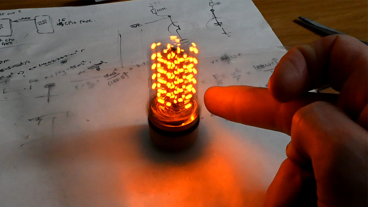
The plan was to machine a base for this device, with a little signpost that would stick up for the IR sensor to catch glimpses of. I realised it worked fine by just holding a finger near it, so never got around to that part. The motor had a very small pulley attached, which was just enough to let it spin up without falling over. I later laser-cut a disk of delrin, just a push-fit over the shaft, which was only supposed to be a stop-gap until I made something on the lathe.
The code steps through the matrix in a columnwise fashion. Looking at the device top-down, each radial line is very slightly spiralled, but that's a lot easier to correct for (if we cared) than having the whole thing be a helix. The duty cycle on the LEDs in the centre is proportionally reduced compared to the periphery.
I quickly got this thing displaying a static test volume. It was only a matter of time before I let it fall on the floor. The 3D print cracked along the glue line.
No worries, we can just keep gluing it back together. It's invincible!
Battery Level
One thing that worried me is that we have no protection circuit for the battery. If it drops much below 3V it will get permanently damaged. (In practice the limit is more like 2.7V, but it depends on the cell. I've destroyed a few through this process.) Most lithium batteries have protection circuits built in, that will disconnect when it reaches a dangerously low level. Not so, with a bare cell. At the very least I wanted to monitor the battery voltage so we can alert and fail to run if we think it's too low.The normal way of monitoring supply voltage level is to add a potential divider to get it into a readable range of the ADC. The Pico boards I think normally have this wired to one of their GPIO, but not the RP2040-tiny. I added two 100K resistors to power and ground to our last available GPIO.
The problem is, there's no reference voltage on the Pico. There's an external pin (not broken out on the RP2040-tiny) that can be used, but if the ADC reference is just its supply voltage, then when the supply voltage dips we won't be able to detect that. At least, not well.
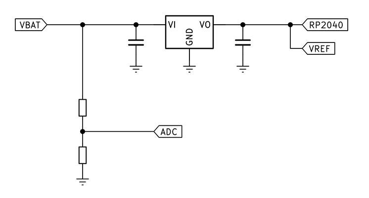
The 3.3V LDO regulator has part number RT9193-33, and a dropout of 220mV at 300mA. That means when the battery voltage reaches 3.52V, our RP2040 supply voltage will start to droop as well. The ADC reading as a function of battery voltage will end up something like this:
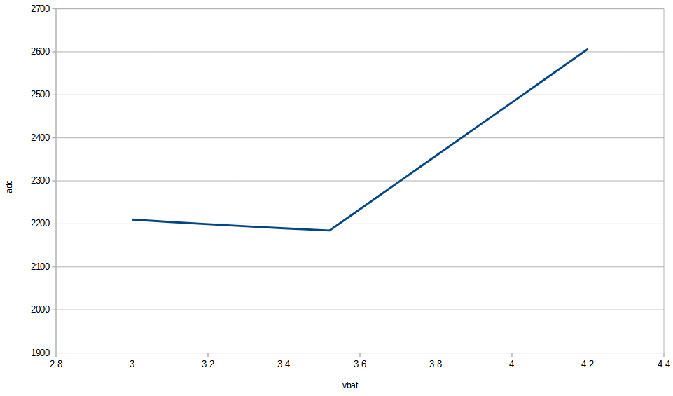
Of course, the dropout voltage is a function of current load, so it isn't even as predictable as that. For this prototype, I made the device show a warning when it reaches just under 3.6V. That's the only thing we can really do here. For the next version, we'll add a reference voltage. It may even be possible to connect the ADC ref to the Pico's internal 1.8V regulator. That would be enough.
Battery charger
The concept was to pop out the LIR2450 when it gets low and stick it into a standalone charger. I bought a standalone charger. It broke the very first time I used it.I was pretty pissed off that a brand new charger would let me down (it wasn't even the cheapest!). And this, at my most excited moment, ready to display more volumetric data! Woe is me!
I 3D printed another battery holder, this time in the other plane. The spring tabs are technically flexing in the weakest direction, but they're generous enough and the wall thickness is all 1mm now.
I wasn't planning to use this for the display, this is just my new battery charger. I set the bench power supply to current limit of 50mA and constant voltage of 4.2V. This is enough to charge a single lithium-ion cell. The constant current is on the conservative side, I wasn't sure if this was a 120mAh battery or a 60mAh battery. It's best to charge no faster than about 1C unless the battery says otherwise. But it's generally never a problem to charge slower than 1C.
This got me fired up again, and the volumetric journey continued. But before we resume the narrative, let me just add that removing the battery and connecting to a power supply is the least convenient way of charging the device, especially after the prototype cracked and I had to add that rubber band to stop the battery flying out.
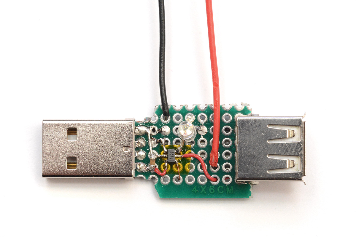
The RP2040-tiny USB adapter board was still being used to load code onto the chip. If we build a kind of USB-intercept board, we can lift the 5V line, and expose the pins for the battery. This sits between the USB cable from the PC to RP2040-tiny programming board.
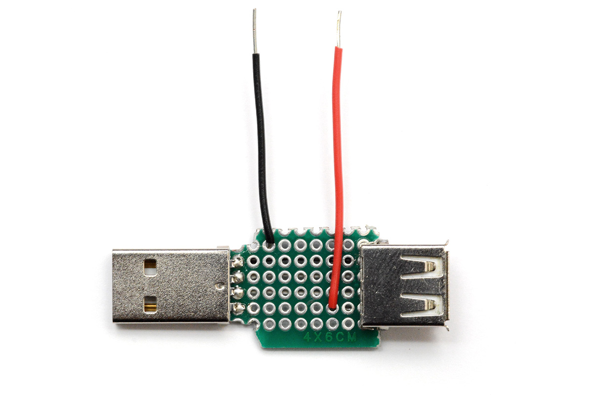
Now we can connect the power supply to the battery without removing it from the prototype. The data lines are still connected underneath, so we can program it with the battery in place as well.
I realised that soldering this up was a waste of time as I could have simply put wires on the RP2040-tiny adapter board.
However in the mad frenzy induced by the working volumetric display, and the kicking of myself for only having one LIR2450 in stock, I found this still too inconvenient for rapid development. In a drawer somewhere, I had some lithium-ion charging ICs. It took me a moment to find them. These are quite nice quality ones, which cost about 90p each. The part number is BQ21040DBVR. I went back to that USB intercept board, and smashed the charging IC into the middle of it.
With this, we can leave the programming cable connected and it will be charging the battery while we think.
Of course, it won't ever fully charge the battery this way because the prototype never turns off. The IR LED alone is constantly drawing about 9mA. There was a very bright power LED on the RP2040-tiny adapter board, I swapped out the resistor to a 20K to stop it wasting power there. But still, I think even when the prototype isn't running it's drawing about 15mA overall. The charging IC, in the constant-voltage phase, will wait until the charging current drops to 0.1C. As our charging current is set to 54mA, that'll never happen. Also, with the voltage drop across the cable the battery probably won't get above 4.1V. None of this really matters, it's just stuff to keep in mind for the next version.
At last we could start doing fluid simulations!
Generating volumetric data
We need to create our volumetric data in 3D polar coordinates, that is, r, theta and z.I started with a wireframe cube, which should at least be somewhat recognisable. I deliberately rotated it to be on-end, to maximise the awkwardness of displaying it. Really I suppose we should write a vector display routine for the device, that would perform some kind of 3D polar coordinate Bresenham interpolation. There's plenty of info out there about applying Bresenham to 3D, and drawing circles, but we want to draw straight lines in polar coordinates. This sounds like a fun thing to think about but for now let's focus on exporting polar voxel data from Blender.
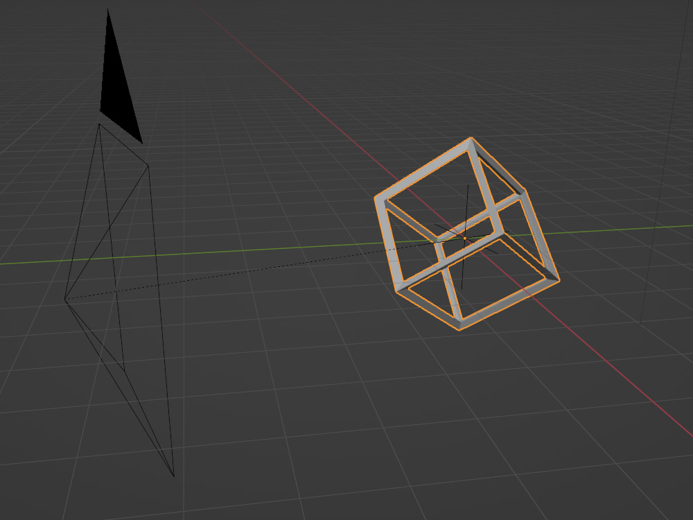
That's the default cube with a wireframe modifier. To rotate a cube to be on-end, with a corner facing directly upwards, we need to first rotate x by 45 degrees, then rotate y by atan(1/sqrt(2)). One of the lovely things about Blender is you can just type in formulas anywhere.
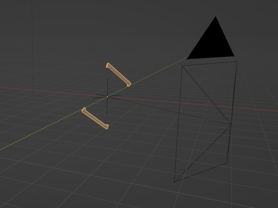
To get slices of this wireframe cube, I added another cube, reshaped it to be somewhat slice-like, and did a boolean modifier between them. I then parented both the camera and this slice to an empty, and animated the empty's Z rotation.
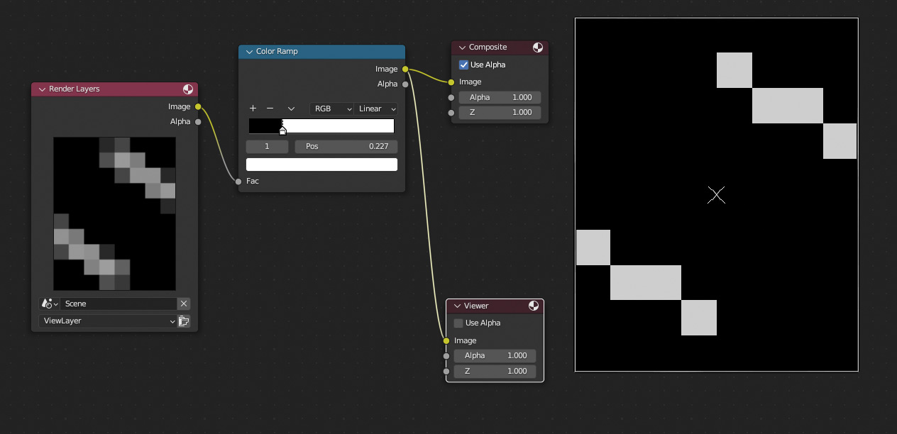
I configured the camera projection to be orthographic, and its resolution to be our tiny 8x10. I set the background to black and the cube's material to emissive. In the compositor, we can use a colour ramp to threshold this. The volumetric display currently has only a bit-depth of 1, so each voxel is just on or off. Thresholding it here lets us visually pick the best cutoff.
"Render animation" now generates 24 images, 24 slices of the wireframe cube. I used a quick python script to chew those up into a header file that can be included in the code.
In Blender, not only can any input accept a formula, and not only can virtually all of them be keyframed, you can also set up a driver. Rather than resolve the formula as you enter it, it will recalculate the result for each frame. So instead of keyframing the rotation of the camera and manually setting it to linear interpolation, I just typed in (frame/24)*2*pi which will loop indefinitely. For the y-rotation of the cube, I now typed in floor(frame/24)*pi/24 so it will rotate a fraction for each full loop of the camera.
Honestly it would have been fine for the rotation to be continuous, but I wanted each frame of data to be discrete, just in case we wanted to adjust playback speed based on motor RPM.
You'll simply have to take my word for it that the display seems a lot more three-dimensional in real life. Looking at the pictures and watching the video it does seem just like a bunch of random dots illuminated. If only you, dear reader, had a volumetric display to experience it on!
Fluid simulations
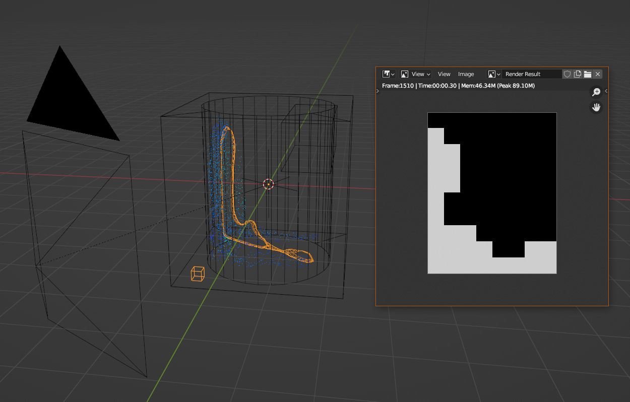
Running a fluid simulation in Blender is both easy and difficult. Easy to get started, difficult to get just right. There are an awful lot of parameters involved.Liquid simulation is slightly easier to port to the volumetric display as it's trivial to convert the fluid particles to a mesh. In theory, we should be able to run a fluid simulation at 1/24th speed, and use the same technique as above to extract polar volumetric data.
Unfortunately using extreme parameters like a very slow time scale leads to instabilities. There doesn't seem to be a straightforward way to play back a simulation at a slower rate, and the very slow simulation speed looks entirely wrong when sped up. I did fiddle around with this for a while with no luck. On the plus side, we're targeting a very low spatial resolution, so the fluid simulations are all fast enough to run in real-time on my desktop machine.
I looked into other ways to render the volumetric data. There's a feature known as Multi-view, or Stereoscopy, that's intended for rendering 3D video. This lets you add two cameras and render a scene from both perspectives simultaneously. It's possible to add any number of cameras, and output all of them based on their naming suffix. I'm not sure if there's a quick way to add 24 cameras and evenly rotate them (sadly you can't apply an array modifier to a camera, I'm not sure if anyone has ever asked for that before) but a further problem with this tactic is that we also need the boolean modifiers of our slices to be rendered at the same time.
Instead of the boolean modifier and a slice, we could cheat a little and use the built-in clipping distances. By setting the camera to only render a 0.1 slice of the scene we get almost the right output. The problem is that only surfaces are drawn, not solid fill for the clipped objects. I thought that maybe applying volumetric material to the objects could make them at least partially filled, but after playing about for a bit I had no luck.
Instead, let's go for a more generic (but more involved) approach: just write a python script. In the scripting tab in blender, I wrote the following:
import bpy
import os
from math import pi

obj = bpy.data.objects['Empty']
output_path = bpy.context.scene.render.filepath

for i in range(24):
  obj.rotation_euler[2] = (i/24)*2*pi
  bpy.context.scene.render.filepath = os.path.join(output_path, f"###_{i:02}.png")
  bpy.ops.render.render(animation=True)

bpy.context.scene.render.filepath = output_path
This way we run the fluid simulation in real time, and simply re-render the whole animation 24 times with different rotations of the Empty (parent to the camera and the slice).
The concept proven, I ploughed ahead with the fire simulation. The way to render this is basically the same but with a couple more steps. We set up our fire simulation, and then bake it in OpenVDB format. Here I set a small cube on fire.
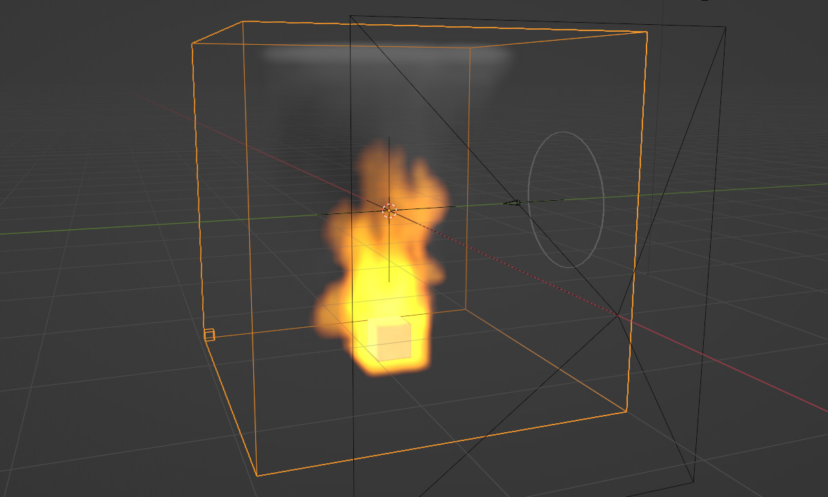
Then start over, and import the OpenVDB data back into Blender. We can then create a new mesh and apply a Volume to Mesh modifier on it, which lets us threshold the volume data. Finally, another boolean modifier with our camera slice, and re-run the script above.
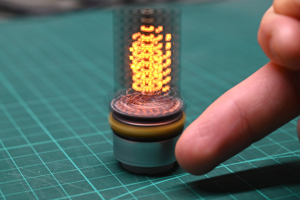
Again, I feel the photograph doesn't really capture the feeling here, but you hopefully get the idea.
It occurs to me that the LED alignment could be corrected for in software, if it were predictable. We could offset the boolean slice either closer or further away from the camera, so that it doesn't spin around the exact centre. If it matched the movement of the real display we should be golden. Similarly, instead of a stretched cube, we could make it a slightly curved shape to compensate for the matrix scanning pattern as the board rotates. At this level of resolution however, I don't think any of these improvements would be visible.
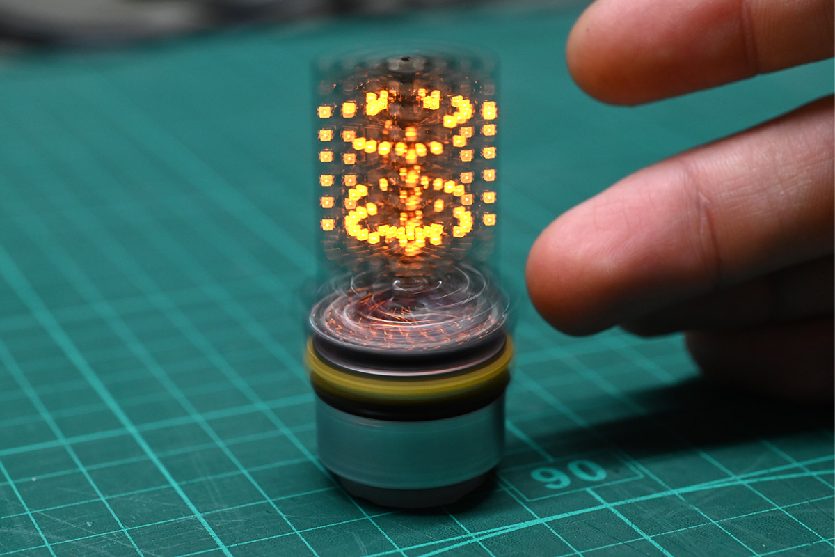
The only thing that really matters is that illuminating an individual voxel near the perimeter should look like a single dot, not a double dot from some angles. You can see it in the image below, where the voxel nearest the camera is elongated because the two illuminations as the matrix rotates didn't quite line up:
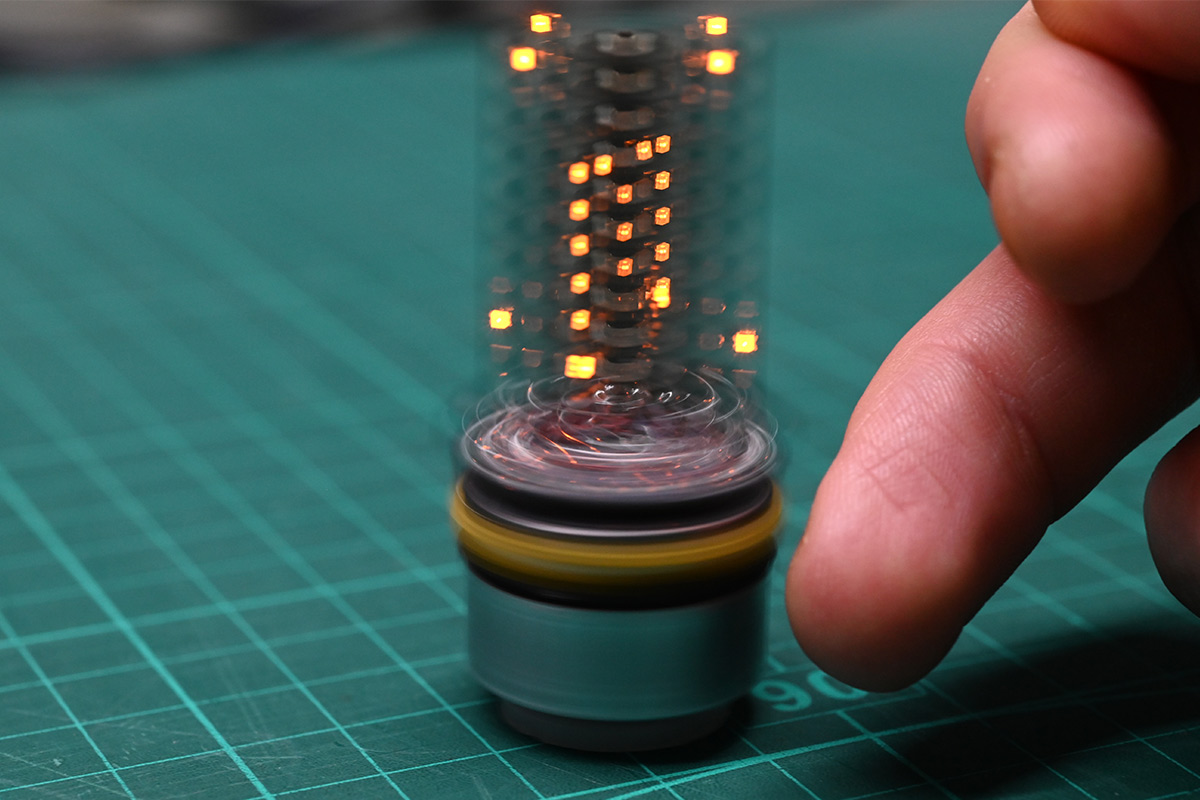
The letter "m" in the centre is perfectly clear, because I deliberately cheated there. To make the text readable from all directions, the text voxels are rendered differently. I made it so the text scrolls in the readable orientation regardless of if you're looking at the front or back of the display. Anyway this voxel discrepancy can only really be noticed on the periphery of the display, where both illuminations are visible at once.
Conclusion, for now
There is plenty of work to do on my fire simulation, but perhaps I'll delay a little until I crank out the next prototype which might be a little better aligned and a little higher-resolution.If I had a tiny slide-switch in stock, I would have added it to this prototype, to disconnect the battery without removing it. I started searching my boxes for something suitable before realising I could simply insert a small piece of acetate between the battery and the contact, like they do with coin cells for IR remotes and so on. That works fine.
On the subject of IR remotes, it would be quite nice to have a remote control for this. We already have an IR sensor, although it's not a demodulating type. As shown in the video, I simply advance to the next mode after a timeout of no activity.
Here are some vanity shots of the device.
The IR is of course totally invisible to the naked eye, but the digital camera picks it up as a faint purple glow.
I have stuck the source code on github as usual.