
Calibrator Keyboard
29 Apr 2023Progress: Complete
Medical equipment and electrometers
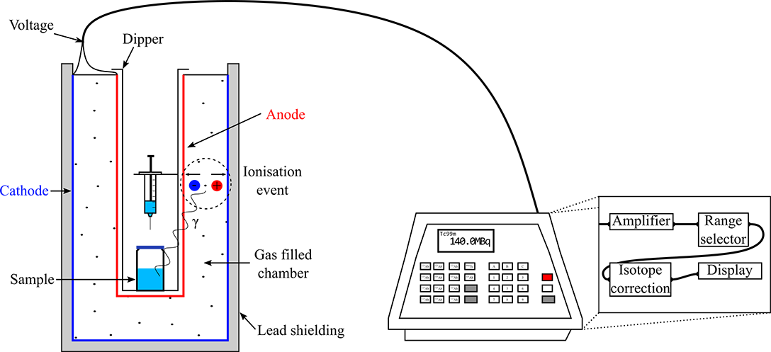
My friend who works in medical physics brought over some exciting broken electrical equipment. The devices are "calibrators", a name that isn't particularly descriptive. The devices are used to measure the radioactivity of a sample in a vial or a syringe.I'm told it's "not quite" a glorified geiger counter, as the ionisation chamber is filled with pressurised noble gas and a much lower voltage is used. The high pressure increases efficiency, and the lower voltage changes the physical effect involved. Unlike a geiger tube, an ionisation event doesn't trigger an avalanche effect. Instead, the small DC current is measured, in direct proportion to the incident radiation.

The ionisation chamber in our case is cylindrical, to almost entirely surround the sample. Wikipedia even has a diagram of it, described as a "nuclide calibrator" or even less helpfully, a "dose calibrator":
The reason I describe a broken one of these as exciting, is that to measure the small current requires some very high quality, low-noise amplifiers. The last time we pulled a similar device apart, the construction was superb, with some very snazzy opamps that I eventually turned into a headphone amplifier. That time, the ion chamber really was little more than a box with a fancy knurled high-voltage connector.
In this case, both ion chambers have a solid physical construction (to contain the pressurised gas) and a fair amount of lead shielding. Since there was a risk of them going bang! during transport, and since the interesting bit is the electronics, my friend only grabbed the control boxes and let the rest go for disposal.
An underwhelming teardown
To our dismay, both units turned out to be entirely boring inside. It isn't even worth me sharing much in the way of pictures.There were two units, one from 1996 and another from 2012. The newer one was noted as being much lower quality and less reliable, while the older one apparently had a solid 25 years of service. But in both cases, the connection to the ion chamber was little more than a serial port. It seems the high voltage circuitry and fancy electrometers were mounted to the chambers themselves.
Still, we tore everything to shreds just in case we found something worthwhile.
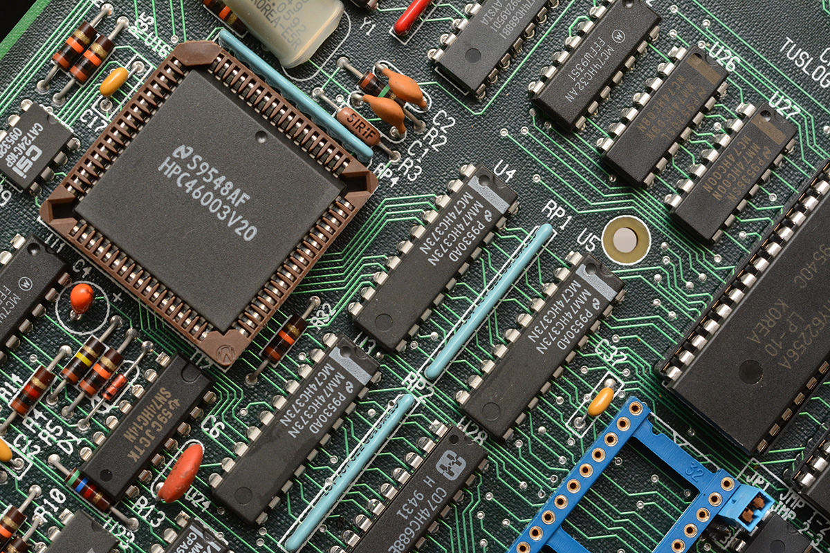
The boards have exactly the sort of construction you'd expect. Microcontroller and support chips, UV-erasable EPROM, bunch of 74-series logic, hardware watchdog, RTC. All these bits would be one IC today. It's one of the things I love about the ATtiny series, that everything it needs is in one DIP package. I never understood why Arduino put an ATmega on a board with a bunch of support components that it simply didn't need, even the smoothing caps are optional. The entire point is that the tiny AVR chips are self-supporting and disposable! Ahem.
Like Proust, when I see circuit designs of this era I can vividly recall the smell of flux and singed epoxy. Many happy childhood hours were spent pulling through-mount parts out of consumer-tier hardware using a blowtorch. The advent of surface-mount boards has deprived a generation of children of these delightfully noxious fumes.
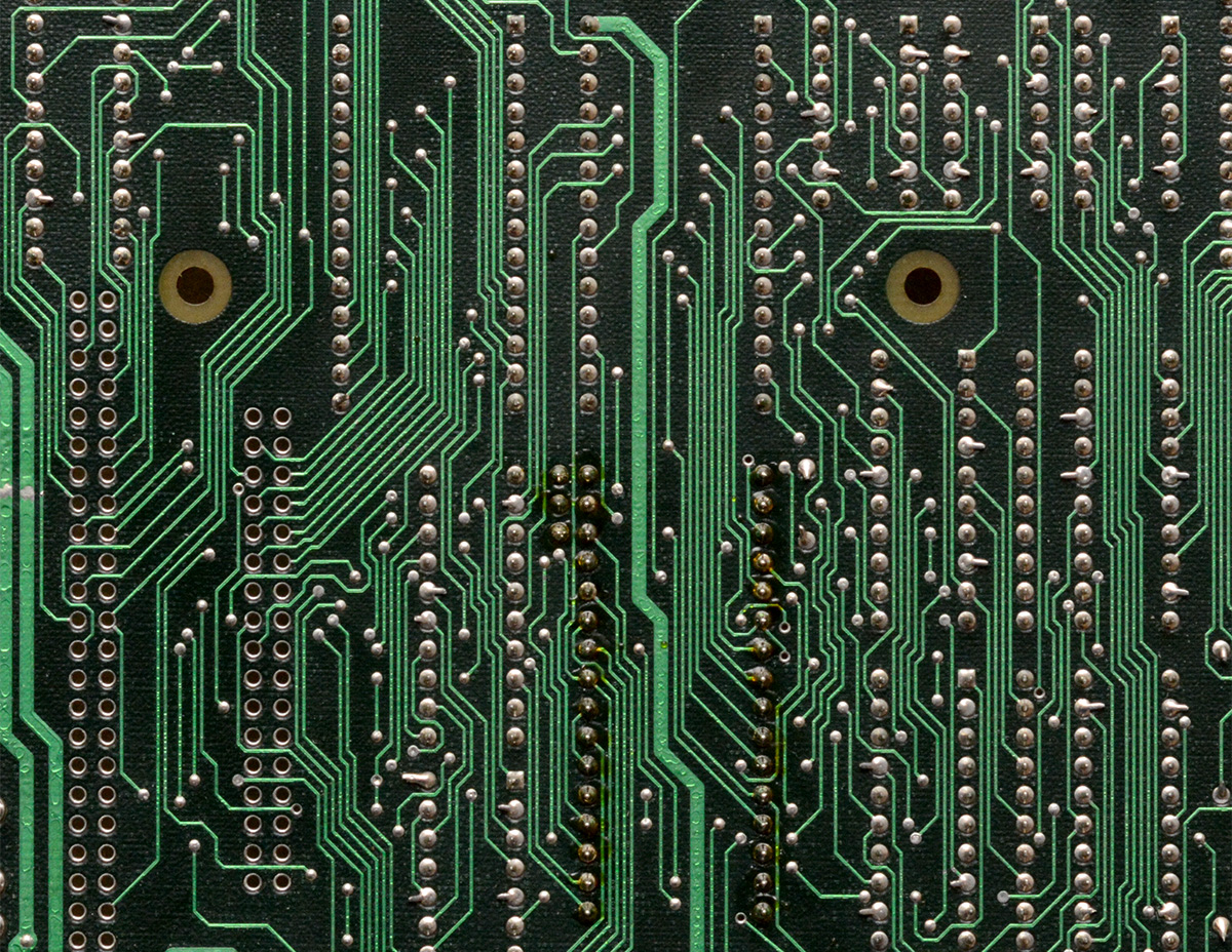
The high contrast is from the ground plane on an internal layer. As is common, they've rigidly stuck to a 45-degree layout except for a couple of places, I can see at least one odd-angle trace in the image above. Not shown in the picture, there was a bodge wire near one edge, typical for small-run PCBs. Flux residue on the legs of the wide DIP part lower middle – I expect the majority of the board was wave soldered, then that component was replaced or reworked by hand.
In the older unit, all of the boards are custom made, but evidently by different people. I think they got the intern to design the LCD controller board. The more I look at it the more it triggers my OCD. The 90-degree zigzags really get to me, especially when there are chamfered corners nearby. It doesn't mean the board is any less functional, but I'm known to be someone who needlessly cares about the visuals.
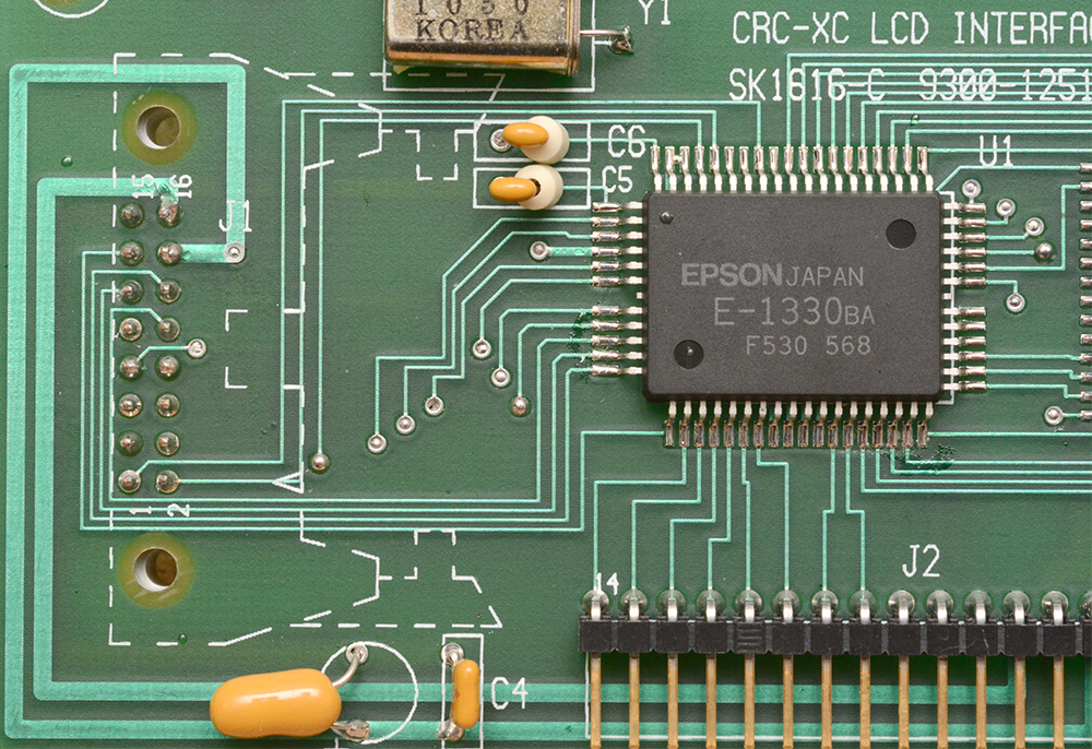
Remember kids, when you design a circuit board, there's always a risk someone will criticise it decades later.
Hidden under their protective stickers, the UV EPROMs hold the firmware. I'm surprised to see a UV EPROM on a product designed in 2012, but I guess manufacturers of medical equipment aren't known as early adopters of new technologies like so-called "flash memory". Wipe off the sticky residue and we can see the die windows.
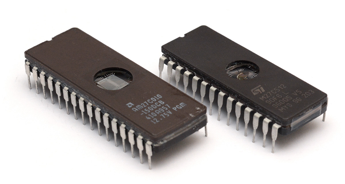
The newer EPROM chip has a notably smaller die.
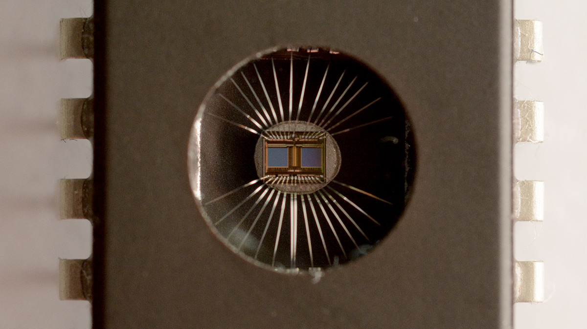
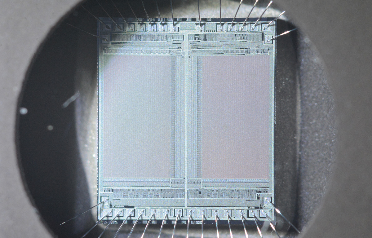
Grabbing the extension tubes (too lazy to set up my microscope imaging arrangement) we can even make out some details on the larger one. The slight pincushion distortion is an effect of the chip window; my macro lens is flawless.
The 1989 date code is clearly visible. A closeup of that corner:
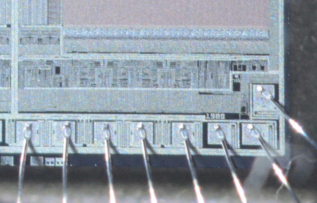
Not bad for a hand-held shot.
To make something of it
We'd timeboxed the afternoon to do something with this junk, and over a game of cribbage it was remarked that the most interesting bit was the keyboard. The newer unit had a horrible cheap thing, but the older one had chunky retro buttons which, although still a membrane keyboard, feel quite satisfying. And the PCB supporting it was one of the more aesthetically pleasing of the bunch:
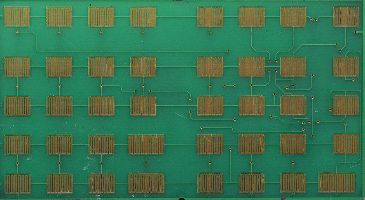
It's a really thick board, 3.2mm of FR4, with no logic, just a header to the labelled rows and columns. It would be very easy to turn this into a USB keyboard or macro-pad. Perhaps that's what we should do?
I ripped up one of the ribbon cables and soldered it to a Raspberry Pi Pico, and stuck it in place with 3M tape.
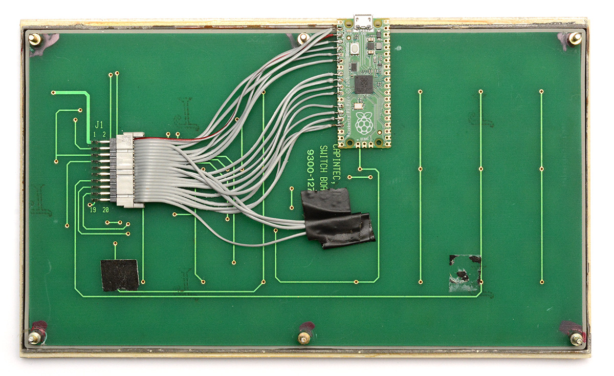
The taped wires at the bottom are not connected. The 'home' key on the keypad was wired independently, I guess to trigger an interrupt. I soldered its wires to the row/column it would have been in, to simplify things. The board originally had threadlocked nuts holding it together, I replaced them with those brass M3 standoffs that came from somewhere else in this pile of junk.
Opinions on the Pico
It occurs to me that this is the first time I've mentioned the chip on this site. I've used it a few times now, enough to make up some opinions on it.The main selling point is that it was pretty much the only microprocessor consistently available at a reasonable price throughout the chip shortage. Despite being newer and vastly more powerful, it's cheaper than most of the ATtiny chips now.
They have done a good job on the documentation and the SDK is easy to use. I've had enough bad experiences setting up toolchains in the past to always dread this step, but it was painless. This is partly because I'm now more familiar with how these things tend to go, but in the past I've used proprietary SDKs that cost ridiculous money that were much more painful to get working than this.
The dual-core stuff is very easy to use. I like the 32-bit GPIO bus, you can sample or update almost all the GPIO in a single clock cycle. I haven't played with the PIO yet.
The UF2 bootloader is great, and particularly useful that it's the default way of loading firmware. I like being able to hand over a circuit and know that remote firmware updates are easy, even if the client is non-technical. This has been possible for ages using custom bootloaders on STM32s and AVRs, and some NXP chips have a rom bootloader that uses USB MSC, but something about the Pico's approach is just far more reassuring.
There's no floating point unit. As a compromise, they've included software floating point routines in the ROM, so using floating point calculations won't pad your code size, it will just run slower than proper hardware support.
A surprising design decision is not to include flash memory onboard the main chip. I suppose the overall feeling is that hobbyists will only ever use the breakout boards, but this means if you want to use the RP2040 chip in your own design you need to add a separate flash memory chip (along with other support components). This is quite against the principles I described earlier about the ATtiny series, how a single chip can do everything and doesn't need support parts, and how great that is for hackers and experimenters, and how brilliant it is to drop one into a tiny circuit. We won't be doing that with the pico for now. But the breakout board is still reasonably small, and is considered a "component" in some ways. You can buy the Pico on a reel, ready for pick-and-place assembly onto other boards as a castellated module. Again, it's an interesting compromise that I don't necessarily dislike.
What I would most like to see is a miniaturised version of the RP2040, with everything onboard in the smallest QFN package possible.
QMK
So we'd wired up a pico to the keypad matrix. In theory, we should be able to dump QMK on there and call it done.QMK is an open source keyboard firmware that supports a huge number of devices and is infinitely customisable. I've seen multiple homebrew mechanical keyboards make use of it, and at least one of those used a Pico as its brains.
If we want this to be a genuine macro keypad, QMK is the way to go. It supports just about anything you could ask for. Unfortunately, that comes at the cost of complexity.
Our keypad is a simple matrix, which means it won't cope with multiple keys being pressed at once. Most keyboards have diodes inline with the switches, but this shouldn't be a problem, QMK can be told not to expect diodes. The rows and columns are wired to the nearest, most convenient GPIO – I soldered it well before checking what might be standard. Again, this shouldn't matter, we can tell QMK where the rows and columns are.
But I struggled to get it to work. It doesn't help that the documentation is something of a mess, with parts aimed at users and other parts aimed at developers, but it's not clear if "adding a new keyboard" puts us in one camp or the other. There are multiple ways of doing the config, the older method using config.h and a newer JSON format, both seem to be used to varying degrees. A "keyboard" is different to a "keymap" so perhaps we could claim it's an existing Pico-based keyboard with a different keymap. The expected way to compile firmware involves using their userspace qmk utility to set up the environment, which doesn't sit well with me. It took a surprising amount of time to get anything to compile.
The real problem is that support for the Pico was only merged in fairly recently so in many ways we're on our own. There are a number of websites that act as QMK configuration utilities, both to do GUI-based keyboard layouts and even to compile the firmware for you – except the Pico is too new to be supported by them. I was almost tempted to unsolder the Pico and find an Atmega chip to use instead, but, well, that would be silly.
I feel like we almost got this working, and I'm sure we can manage it in the future, but after a while it stopped being fun and since the entire project is a joke, I thought it would be easier to just make a keyboard firmware from scratch.
Python??
A lot of people have sung the praises of MicroPython and CircuitPython on the Pico. In fact, a few people have raised eyebrows at me for programming it in C. Most of my projects have needed timing-critical aspects or more advanced usages that rule out python immediately, but a keyboard is simple enough that it should be fine.
At first glance, it does look quite straight forward. It should be as simple import usb_hid, the libraries should do all the heavy lifting for us. The bit I balked at is it doesn't look possible to sample or set all the GPIO at once. With digitalio, if you want to set ten GPIO pins high, you need to write out the command ten times over. That seems unlikely, but I'm not going to tediously write a keyboard matrix routine under those conditions.
I later spotted that there's a Keypad library too, so perhaps that's the way to go. But let's not kid ourselves, there wasn't much chance I'd really consider doing this in python.
Let's C the matrix
Our keypad has 8 columns and 5 rows.

If you google how to read out a keypad matrix with a microcontroller, you will invariably find guides that tell you what I would describe as the boring, slow way of doing it. They suggest:
- Set only one row active (output low, if the inputs have pullups), and read out which columns are activated
- Set only the next row active, and read out the columns again
- Set only the next row active, and so on
I'm surprised to see almost no mention of the fast way, which I'm certain I didn't invent. Perhaps the technique has a name that I'm unaware of. Perhaps it's so inconsequential that no one cares. It goes like this:
- Set all of the columns active, and see which rows are activated
- Set all of the rows active, and see which columns are activated
That reads out the whole matrix in just two operations, no matter how many rows or columns you have. Given that any change in the outputs may warrant delays while the levels settle, reducing the number of changes could mean a significant speedup. If that mattered. Which, of course, it doesn't, and I'm doing it the fast way simply because the slow way offends me (and takes longer to write).
As a modern microcontroller, the Pico offers both pull-downs and pull-ups on its inputs (and CMOS outputs), so we might as well make our signals active-high. We can initialise the GPIO with all outputs high, and all pulldowns enabled, then just toggle from input to output to do the scan. Once we've got our (row, column) input we just progressively shift it to get an (x, y) coordinate of the key pressed.
// GP1 to GP5 : rows
// GP6 to GP13 : columns
const uint32_t row_pins = 0b00000000000000000000000000111110;
const uint32_t col_pins = 0b00000000000000000011111111000000;

uint8_t scan_matrix(){

  gpio_set_dir_out_masked( row_pins );
  gpio_set_dir_in_masked( col_pins );
  sleep_us(100);
  uint32_t cols = (gpio_get_all() & col_pins) >>5;

  gpio_set_dir_out_masked( col_pins );
  gpio_set_dir_in_masked( row_pins );
  sleep_us(100);
  uint32_t rows = (gpio_get_all() & row_pins);

  uint8_t x=0, y=0;

  while (cols >>= 1) { x++; }
  while (rows >>= 1) { y++; }

  if (x && y) return keymap[y-1][x-1];
  return 0;
}
It's no coincidence I'd skipped GP0. Both x and y are 1-indexed, so an x or y of zero means no key was pressed. On the other hand, there is no key at the top left position, so caring about it is moot. The last thing to do is debouncing, which just means after detecting a change, wait a few milliseconds and check it still matches.
To actually register as a USB keyboard, I'll modify one of the tinyusb examples. There isn't a straight keyboard example, so I took the "composite HID device" (which is simultaneously keyboard, mouse, gamepad and "consumer control") and stripped out everything unrelated to keyboard. For the keymap I just did A-Z, 0-9. With that, we're able to type nonsense!

Keymap
It's hard to think of any conceivable use case for such a keyboard.
- A macro pad is the first sensible option, but having never used a macro pad I don't know what people actually use them for. Photoshop shortcuts? Opening webpages? What is this "stream deck" people speak of? Without QMK some OS-side software would be needed, which is fine.
Searching, it seems that some macro pads send obscure keycodes so as not to clash with anything else. There are codes for function keys up to F24. These can also be combined with modifiers (
Ctrl+F13etc) to cover more buttons. But it should be simple enough with whatever macro software you're using to filter by the keyboard's hardware ID, so doing this isn't necessary. There's certainly a lot of Windows software for this: AutoHotKey, HID Macros, GlovePIE, etc. - A terrible typing keyboard. It would be amusing to write this article on it. There's only 36 keys though, and no provision for Shift. I could re-wire the Home key to be a modifier key. If it had proper diodes in the matrix and multi-key support we could do layers like QMK does, with several modifiers to get the full range of keys. But that would be boring.
- An emoji keyboard. It would be entertaining. Unfortunately, it's not easy to do this without making it deeply platform-specific. It's already very hard to send unicode with a HID keyboard, for historical reasons. There is a very interesting response here from one of the original developers. In short, it's based on the PS2 scan codes, and in the PS2 era it was common to ship keyboards with the same internals but different keycaps for different regions.
QMK manages to send unicode characters I believe via multiple keystrokes, in a platform specific way, such as Alt+numpad. In most cases, this only gives you a small subset of unicode, unless you fiddle with the OS settings too.
To get Emojis, we have to do something even less appealing. Existing "emoji keyboards" do it by first calling up the on-screen emoji keyboard, then typing the name of the emoji and pressing enter. This is particularly hideous since it needs a delay, to wait for the on-screen keyboard to come up. And it's customised not just to the OS, but to specific versions of the OS. The windows shortcut is
Win+.orWin+;, the mac shortcut isControl+command+space. - Type words or phrases with each button. Possible via macros of course, but having the hardware do it appeals to me in that quirky way that it's impossible to change without reflashing the board. Plus it's completely platform-independent. If the keyboard is sending multiple keystrokes with each button press, that makes it much harder to remap what it's doing with macro software (which is a comedic benefit).
Lack of customisability on a joke project is always amusing. But what words or phrases should it type? I think the funniest option is to just describe which key was pressed. Nothing is more frustrating than pressing the "Enter" key, only for the keyboard to type the word "Enter". This is the most appealing option yet.
In the end I compromised, the numpad acts as a real numpad (albeit inverted), the nuclides type their name in full, and Enter types "Enter". Cal# is numlock, and the LED on the pico indicates it. Of course when numlock's off, the up/down arrow keys are the wrong way round. The result is just on the cusp of being useful – sufficiently so that someone might actually use this – but not useful enough to avoid making them the target of ridicule. Perfect!
Case
To terminate this aimless adventure, I laser-cut a panel to cover up the loose wires. Bamboo seemed the appropriate material.
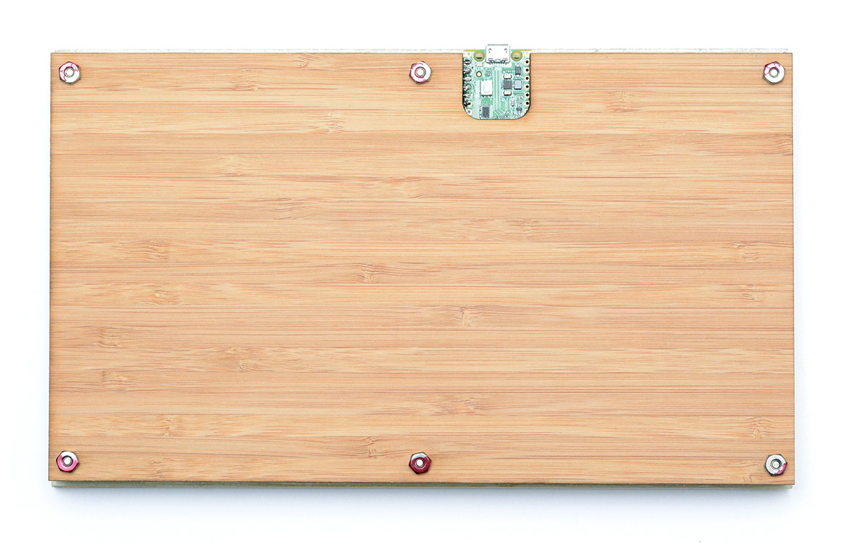
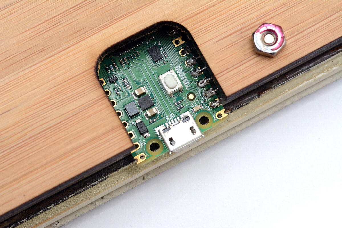
One of the best bits about owning a laser cutter is that the slowest part of this process is measuring up the distance between screw holes. Cutting is so satisfyingly fast. Naturally I made a cutout to expose the boot button so that the victim recipient of this gift can do something less stupid with it.
Source code is on github and git.mitxela.com as usual. See the initial commit if you just want it to be a keyboard.
Yeah, I hear you, the absence of op-amps was a little disappointing. We can cross our fingers for next time.