Brass Infinity Cube
7 Nov 2022Progress: Complete
A friend of mine has a fidget toy called an infinity cube. I saw it (from a distance) and figured I'd try to make a brass one. Here's a video of the construction:
Plan
Not having a reference cube to go by turned the first hurdle into a cerebral one. I suppose the immediate question is: are all the cubes identical? I tried quite hard to picture the mechanism in my mind, from memory, and found it almost impossible to visualize where all the hinges go. Even after looking up a picture of one for reference, mentally rotating and translating it is really hard.
After struggling for a few minutes I turned to OpenSCAD to model what I believed to be the correct hinge placements. This is a static model so the hinges still have to be actuated mentally, but you can pan/rotate/zoom/get frustrated by the gimbal lock with the following embeddiment:
(Update: I have unlocked the gimbals)
It is possible, just by looking at a single viewpoint, to figure out the number of unique cubes. I found it helpful to think in terms of mirror images.
I had a rough idea of how big it should be. I got some brass stock that was three-quarter inch square profile (~19mm), and in the interest of saving time I decided to leave most of the surfaces unfinished. Already this seemed a little on the large side, but I later found out the plastic toy is even bigger than this, pretty much dead-on 20mm cubes.
First two
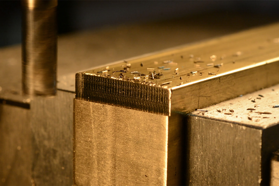
There are a bunch of ways I could have done the hinges; I settled on welding them, using stainless filler rod as the main component. To see if this was even viable I wanted to build two cubes first and link them together.The first thing to note is that chamfering the cubes took ages.
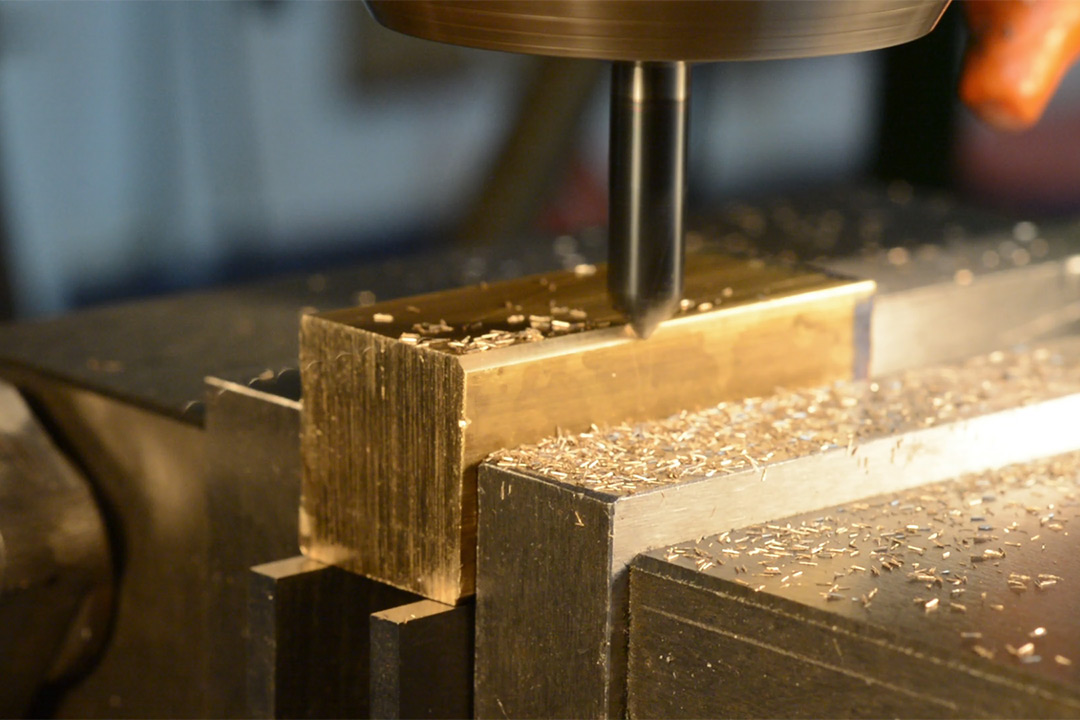
Attempting to chamfer four of the edges along the entire raw stock crossed my mind. I decided it would be too tricky to get the tram just right, since the stock is longer than the vice is wide, and even a slight variation would alter the chamfer width, two cubes at once was as much as I dared do.
The mill has a DRO, and we can lock the axes, so we should be able to just open the vice, drop in the next cube edge, and run the chamfer across. There's a couple of reasons this isn't nearly as fast as it should be, primarily that the swarf gets all over the parallels and you have to wipe it up before you can confidently clamp the cube in the correct place. The other issue is that the cubes aren't perfectly cubic, the unfinished surfaces unsurprisingly have a variation of maybe 100 microns. To get around this I should be doing the chamfer on the rear jaw of the vice, so the dimensions wouldn't matter, but then you can't see what you're doing.
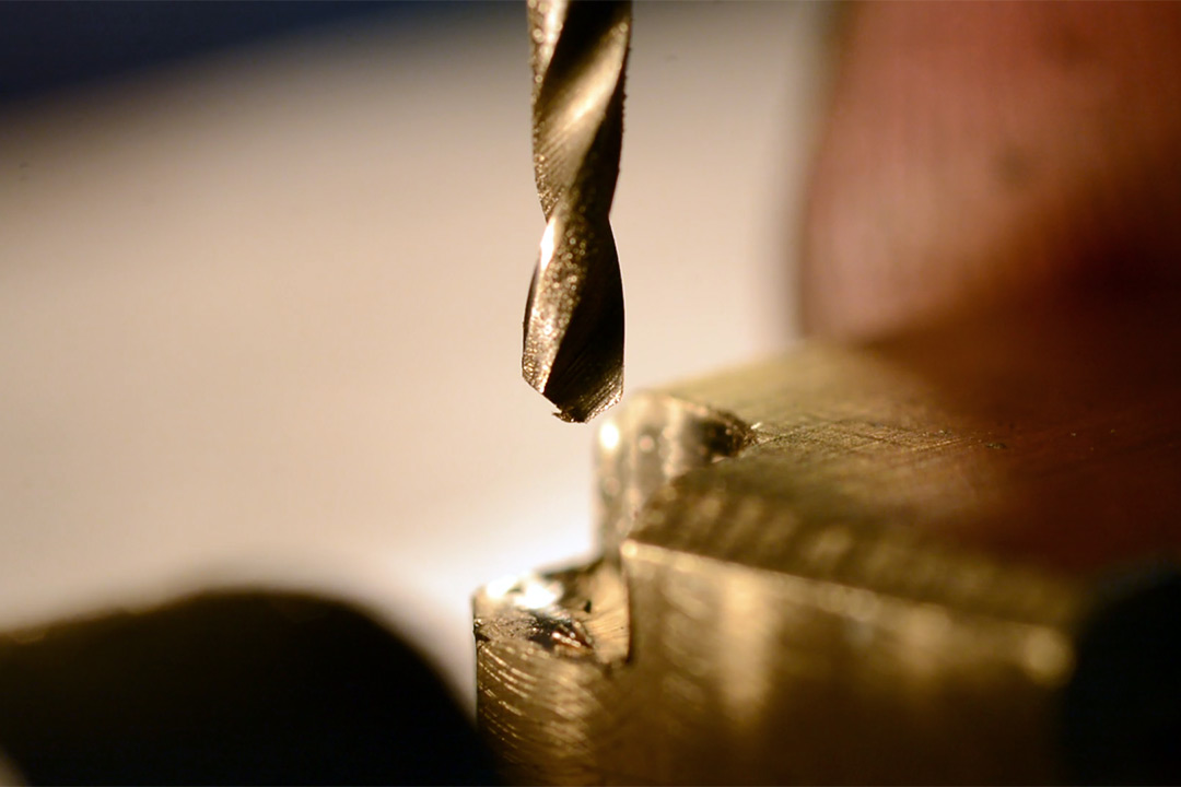
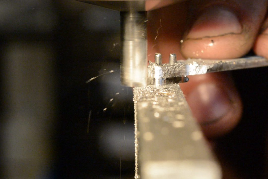
When it came to milling the cutout and drilling the hole for the hinge, I was unsure how much slack to give it. I feel like if the joint was stiff the whole fiddling aspect might get ruined, so I erred on the side of making it too loose, including drilling the hole with the 1.7mm drillbit, for the 1.6mm filler rod.
I considered folding the filler rod into a U-shape and just doing a weld on one side but I think that would look lame.
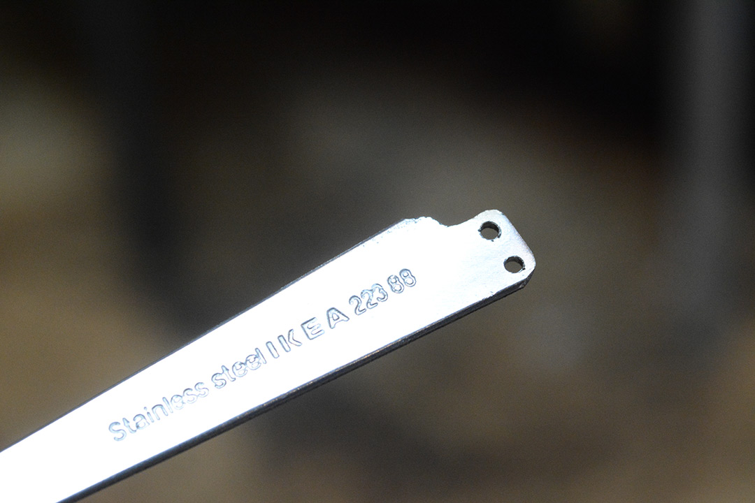
However, making tiny little linkages out of stainless is also very tedious. I made the first two out of the handle of a spoon, which seemed like a convenient source of stainless plate. Given how fiddly it is to hold onto, I determined to eschew this for the later hinges.
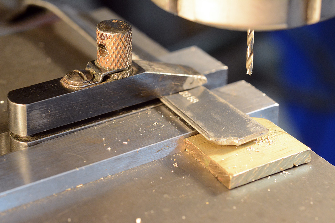
The shape for these two was finished off with the grinder, first holding the rest of the spoon, then holding it with mole grips.
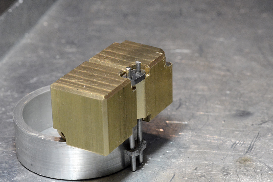
I made the rods a bit too long with the knowledge that I can cut them down. This did mean I needed to find a nice bit of scrap aluminium to stand it on, in order to get the right amount of stick-out.
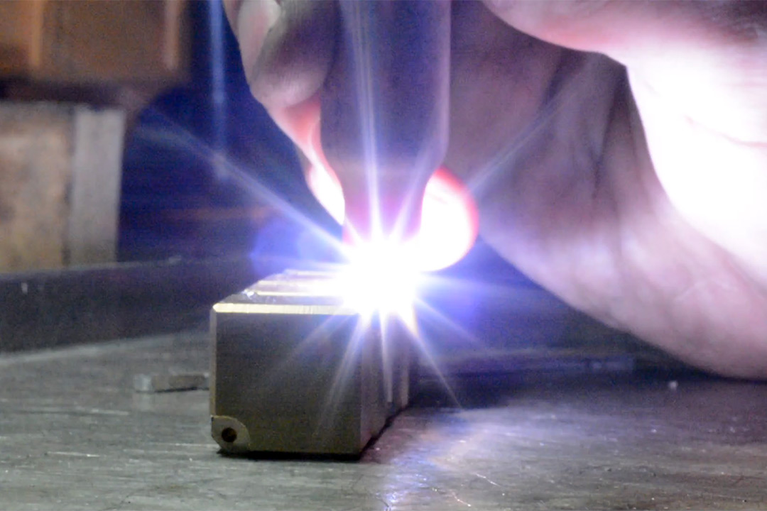
I could have peened-over the filler rod like rivets. I felt like welding it.
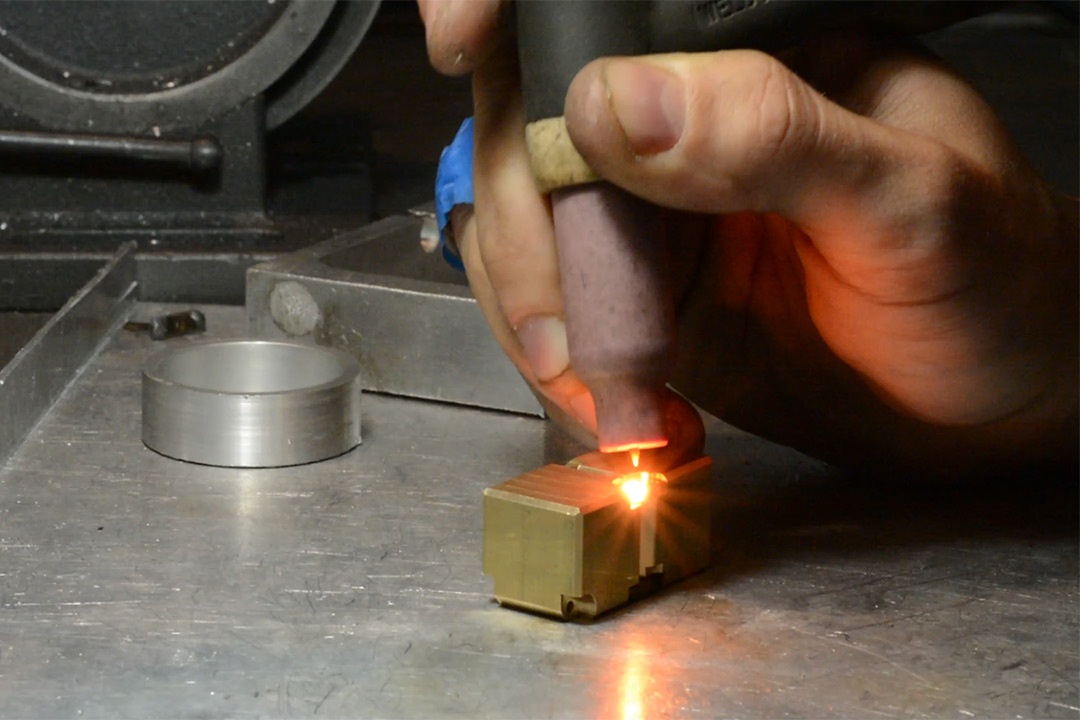
It's stainless, but the weld is not going to look shiny. To clean it up, we'd need to either mechanically polish it (lame), pickle it in some really noxious acids, or electropolish it. I would like to try electropolishing at some point.
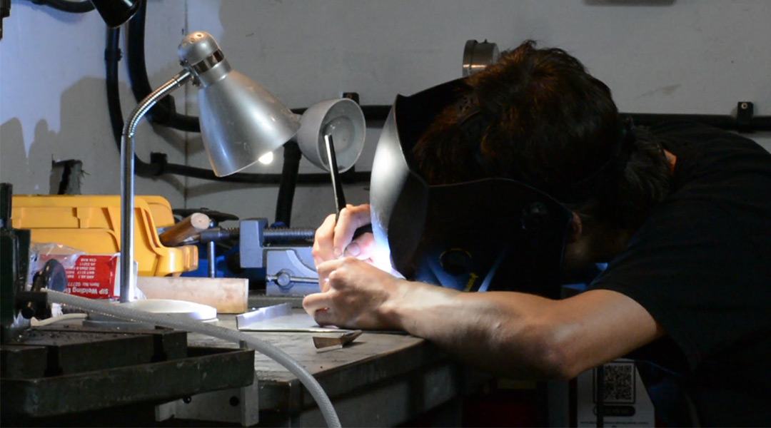
This (somewhat underwhelming) project becomes my first where I've attempted to film welding. I wasn't even sure if I was going to make a video of it (in the past, I've regretted not filming things, so these days I try to film all projects just in case). The conclusion, as I was already aware but unprepared for, is that to film it well you need really bright floodlights, bright enough that there's no real change in light levels when the arc strikes. I tried filming through a welding mask, it was both very fiddly and an unsatisfactory result.
The hinge worked perfectly. Next I needed to just do the same thing an infinite number of times.
Production Cubes
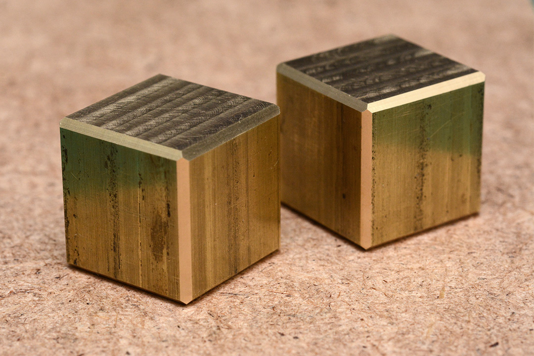
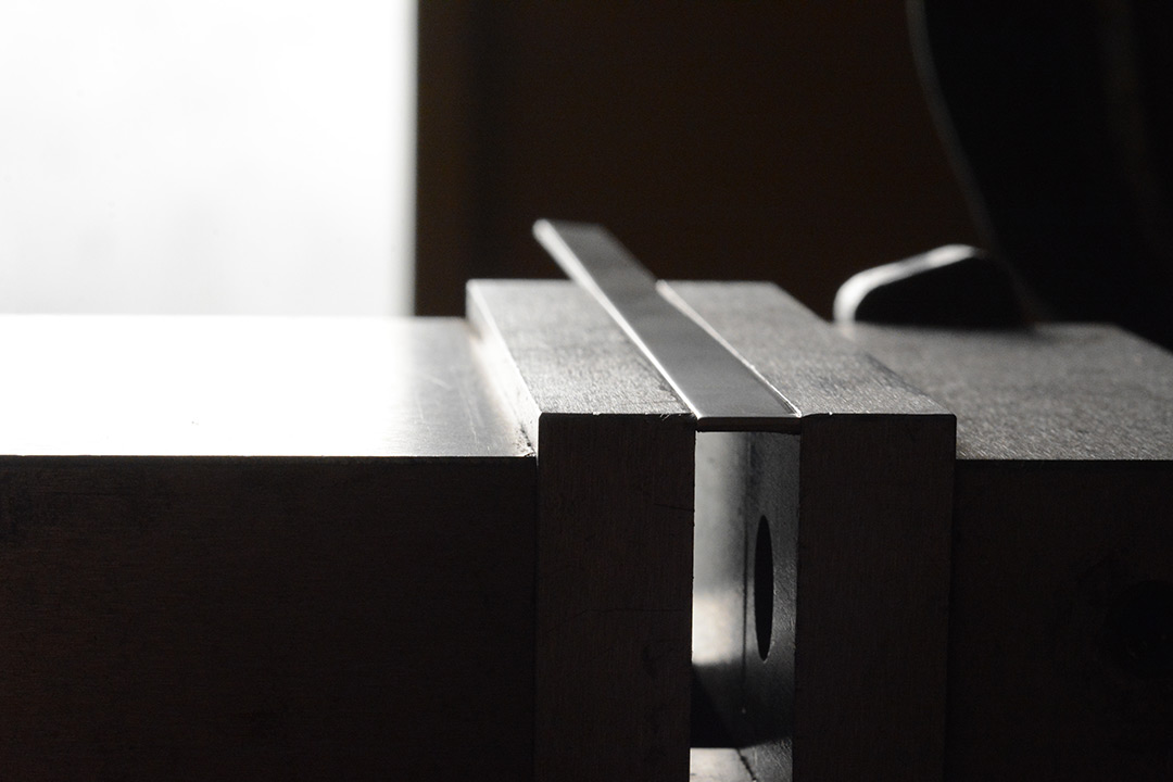
For chopping up stock, the donkey saw was called into action, which is like a bandsaw but worse. I was impressed by it though, the cut was sufficiently perpendicular that by the last few cubes I was comfortable leaving only half a millimetre spare.Importantly, to speed up the squaring process, I milled a single flat into the stock before each cut.
This then gets used as the reference surface for squaring it up, using a single parallel.
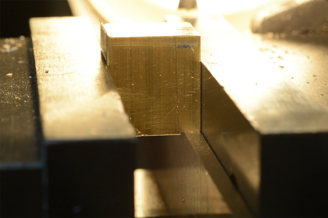
Doing it this way specifically avoids depending on the tram of the milling head. The only alignment I personally checked was that the vice jaw was aligned with the X-axis. If we completely squared up the end of the stock with the milling cutter, it wouldn't be perpendicular to the Z-axis, because this is a communal milling machine that people treat like crap. I've trammed the head in the past, it takes ages and the next time I go to use it it's off again. The X/Y axes will always be perpendicular (at least within the tolerance of the machine) so this method is a reliable way to make things as square as we can.
Production Chamfers
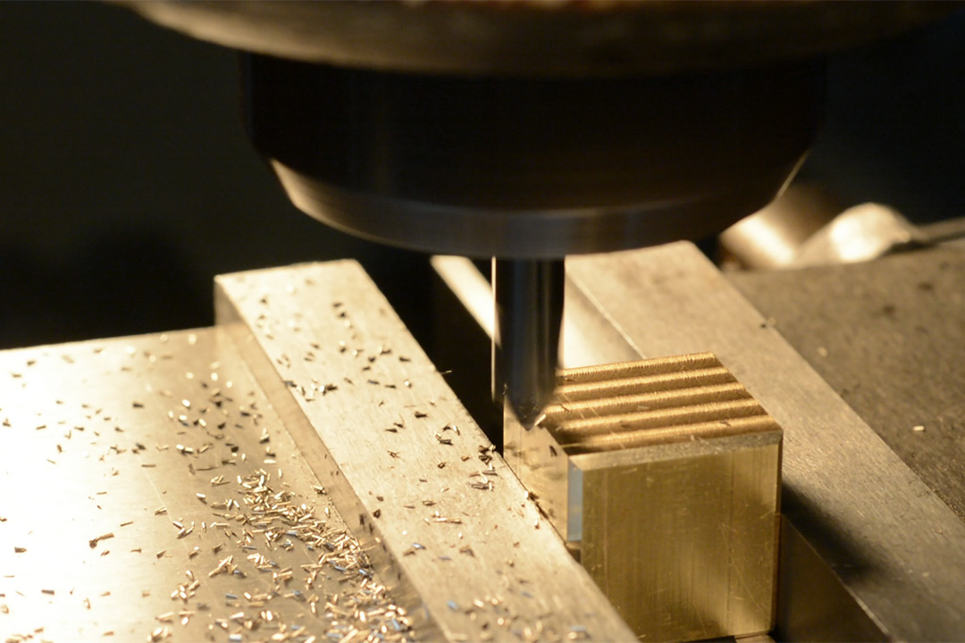
With the prospect of manually chamfering a further 72 edges (followed by 12 deeper chamfers for the hinge edges) a jig was in order.
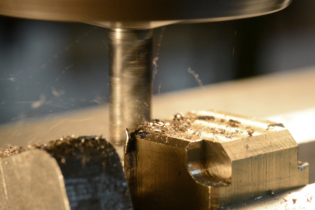
I pretty much turned the machine into a router table. That's the edge of a 6mm carbide endmill poking through the slot. Importantly, by building it this way, it is impossible (unless the jig breaks) to cut too much away. If there's chatter, the cut will be too shallow, and you can just pass it across again. And doubly important, all of the swarf gets ejected out of the back, so we can plough through the chamfers with no downtime.
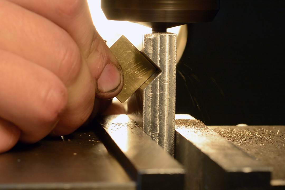
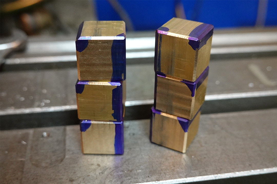
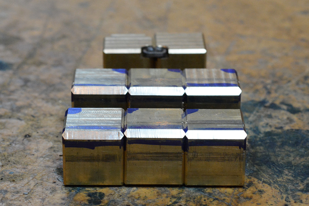
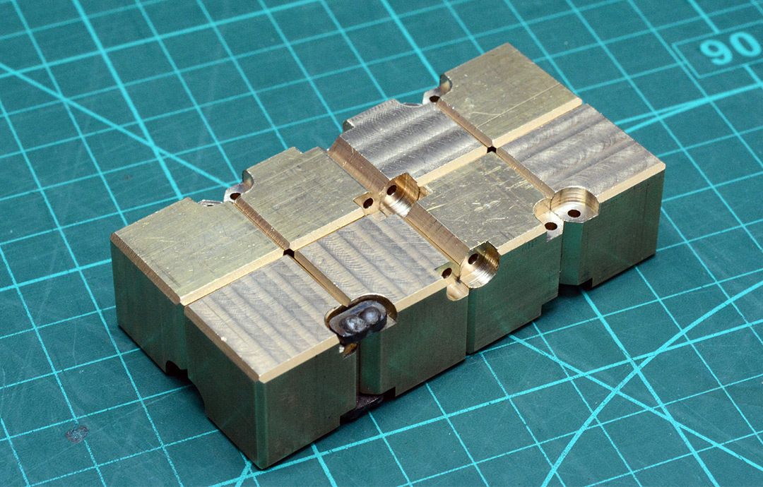
This ingenious jig, if I dare call it that, worked spectacularly well. For the deeper chamfers on the hinged edges, it was a little tricky to go to the full depth at once, but rather than moving the cutter in and out each time, it made more sense to move it in a little, run all of the cubes through it, and then move it in a little more. The DRO makes either method valid, the only thing that matters is that we mill the right edges. This is where all that thinking earlier comes into play. Of course, we know they all need at least one hinge (which can go anywhere), it's the placement of the second hinge that matters. I marked the edges with sharpie, including the corners where it's hopefully less likely to rub off.
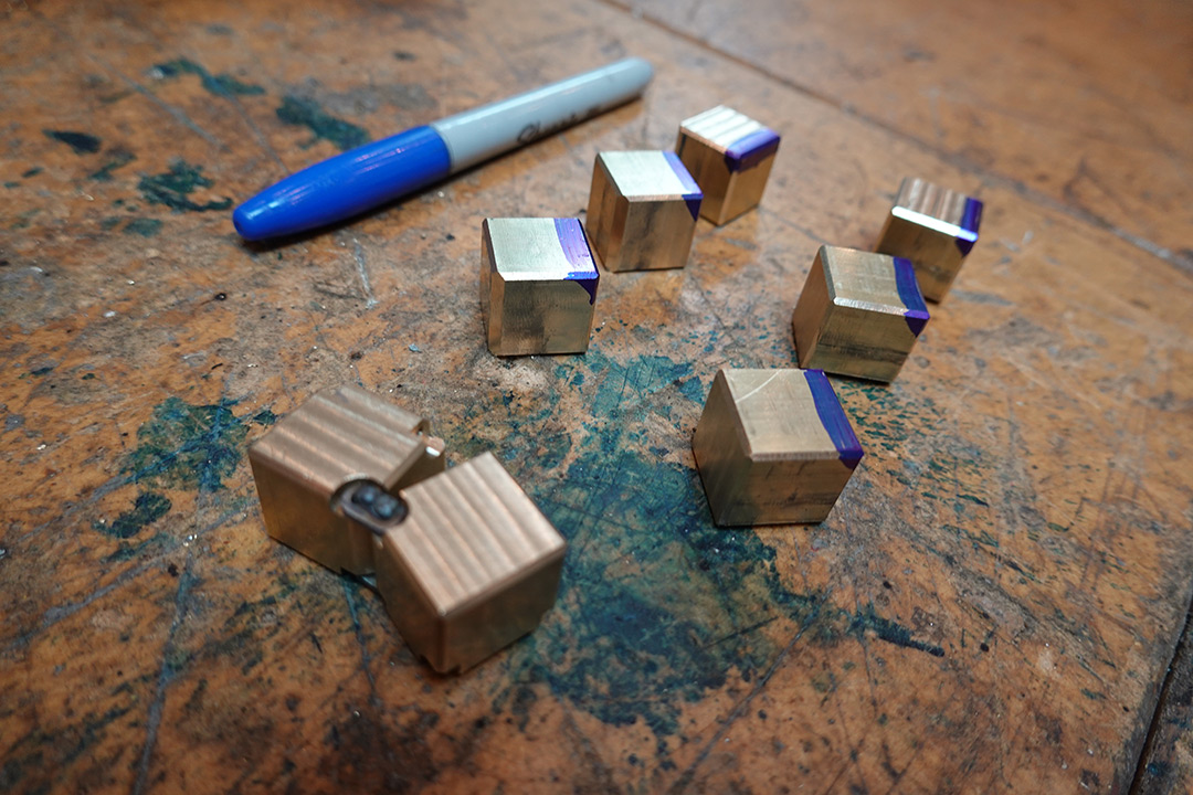
If you're still wondering about the topology of the situation, my grouping is probably a spoiler for the answer of the number of unique cubes.
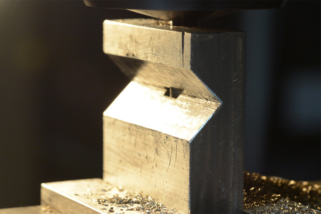
Production Hinge Cutouts
There isn't really a shortcut to doing these quickly. Using the depth stop on the vice means we can reliably drop a cube into place and repeat the operation. Another topology question to bake your noodle: are all the cutouts identical?
The thing that really slowed this down is needing to vacuum up the chips each time, and the predicable creation of a large burr which really needs to be scraped off before the cube can be clamped again. I ended up doing just one corner of each cube, then scraping off all the burrs, then doing just one more corner of each cube, and so on.
Given the time cost of spot-drilling the holes before we drill them proper I decided to just go straight to the 1.7mm drillbit and plunge each of them in turn. No doubt some of the holes wandered, but we're not aiming for precision hinges here, if anything, having the thing loose like a chain is more of the feel we want to go for. Additionally, drilling each hole only halfway and then flipping it over significantly limited the amount of wander.
The drillbit was mounted in an ER32 collet. The reason I prefer collets for drillbits is not the one you're probably thinking (runout). It's primarily because the drill chuck is so large that it effectively extends the quill by 20cm. As mentioned earlier, the tram on this mill is never spot-on. The odds of the Z-axis (knee) being aligned with the quill axis to within a few microns over 20cm is laughable, so in effect if you drop the knee to fit a drill chuck you can forget whatever the DRO says and will need to dial it in again.
In retrospect, the only thing that would have really sped up the production line would be to have fitted a little vaccum nozzle right near the bit. The ever-present danger of trapping some swarf between the vice jaws and the part really put a cap on how fast I could do this.
With the cubes completed, and only the hinges left to do (and only spoon handles to make them from) I called it a day at this point and went to bed.
Production Hinges
1.5mm stainless plate is not expensive, and the comedic benefit of making the hinges out of spoons does not, in fact, outweigh the cost of having a really tricky time holding them. I produced a 9mm strip of fresh stainless steel plate using a guillotine.No matter how careful you are, it's impossible to get the guillotined edges perfectly parallel. The piece also ends up twisted, which needs bending back with pliers. One end of the part is very slightly wider than the other – that's the side that'll be gripped strongest by the vice and so the side we want to drill our holes in.
Drilling holes in stainless steel is always a challenge. Go too slowly, and you'll work-harden the material making it extremely hard to drill. Go too fast and you'll overheat and probably break the drillbit.
At least this way, compared to the spoon, we can drill a whole bunch of 1.6mm holes without having to regrip the part, and then (following some tedious deburring) slice each one off with the guillotine at the end.
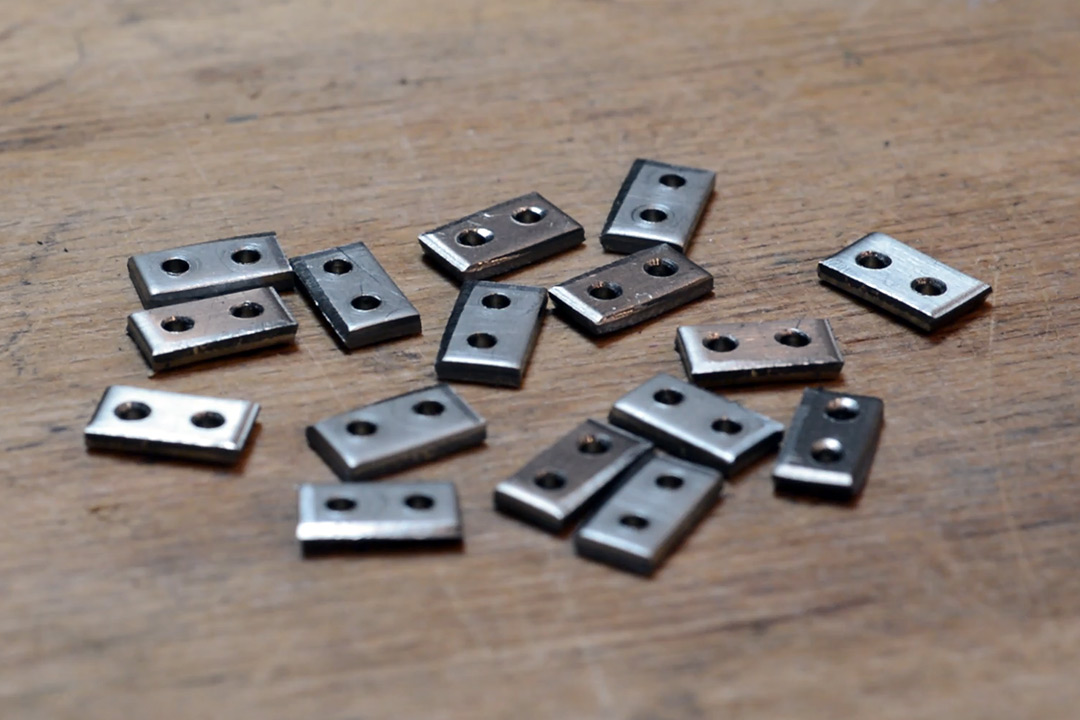
The corners need to be rounded. They don't need to be tidy, but they need to not foul the cutouts in the cubes. Another jig is in order!
This jig was just a strip of aluminium with two holes in it. One holds a long peg, which the jig can rotate around, the other holds a short peg which constrains the rotation of the hinge linkage. With this, I can mill the parts to size and round the corners. Each linkage needs to go through the jig twice in order to round both ends.
It still took bloody ages, well over an hour to do all sixteen linkages, but that's still shorter than it took me to make the original two out of spoon handles. Technically I only needed to make fourteen, but I was banking on losing at least one or two in the rounding process so made a couple extra at the drilling/guillotining stage.
Finally we need to weld all the cube hinges together, in the correct order, and hope that our topology skills were up to the task.
If you're wondering why I'm not wearing gloves, they're simply not needed at these power levels, especially considering the total combined arc time is well under twenty seconds.
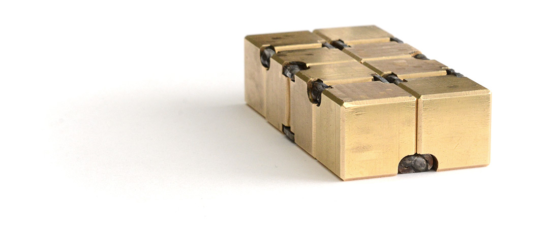
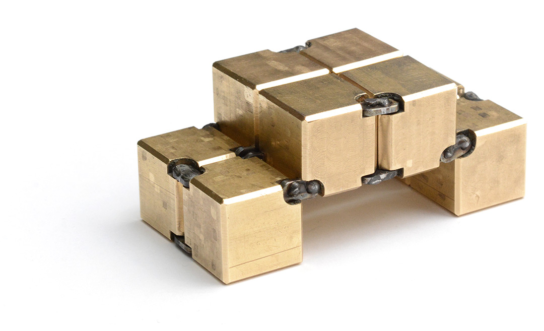
There was a moment, having connected four cubes together, that I weighed it in my hand and decided: yes, this is about the right weight for an executive toy. Double this amount is going to be too much. Oops!
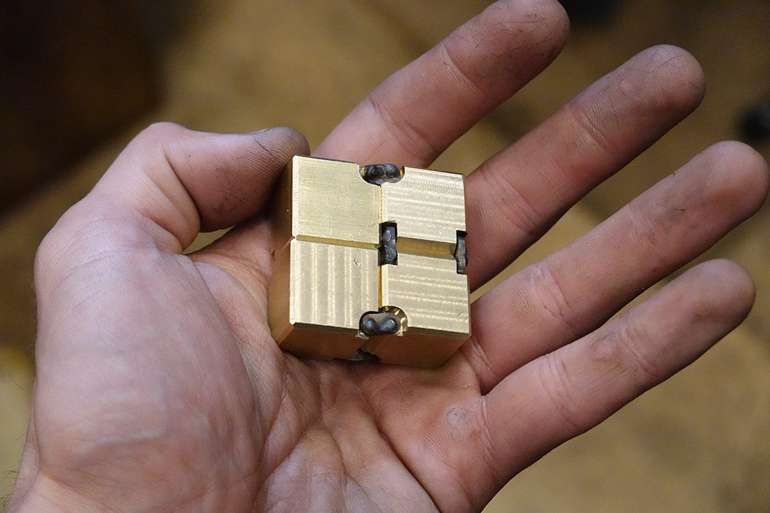
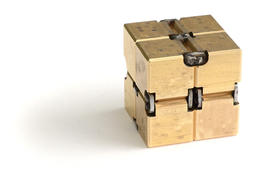
Completion
It is a weighty infinity cube.
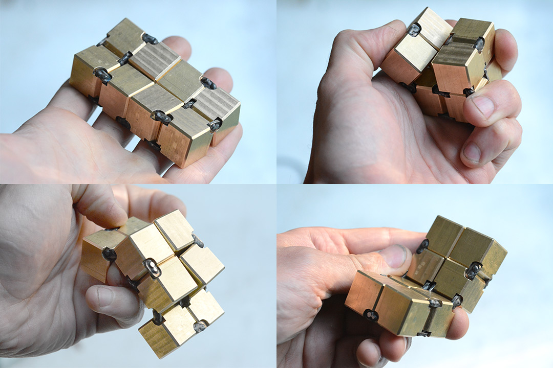
Half a kilogram (~1 lb) might not sound like a lot, but it quickly gets tiring!
After a few hours of playing with it (dropping it on the floor more than once), some curious wear patterns started to appear.
The rectangles are possibly due to dirt/dust/swarf getting trapped between the cubes as they cycle, and the somewhat rectangular slop of the hinges guiding them.
The hinges gradually loosened over the first hour or so, as the high spots wore down. I don't think I needed to worry about making it too stiff, the links feel more like a chain than like hinges. I probably could have gotten away with tighter tolerances.