
Bleps via State Machine
28 Jul 2022Progress: Complete
In 2020, I produced a new algorithm for the flash synth that turned it into a subtractive synthesizer. The system is so limited that this warranted the creation of a new kind of BLEP (band-limited step) for producing square and sawtooth waves.
The algorithm produces identical output to the near-ubiquitous 2-sample polyBLEP, but with a fraction of the overhead. I was so pleased with my results that I scripted a lengthy video explaining how it all works, starting from the very basics. However, it's now been two years and I still haven't finished producing that video, so I think it's time for me to post a written summary instead. Most of the video involved explaining fourier transforms and why square waves are so hard to produce digitally. I may finish the video one day, but for now here's the juiciest bits.
Why are square waves so hard to make? A quick summary
With a simple electrical circuit, a square wave is very easy to make. But in the world of Digital Signal Processing (DSP), or pretty much anywhere where a samplerate is involved, producing a square wave is astoundingly difficult. Believe it or not, academics are still publishing papers on better ways to solve this problem.Sounds are vibrations in the air. A microphone or speaker is just a membrane and a circuit to read out or set its position over time. This is operating in the "Time Domain". Recorded sounds have a waveform that corresponds to air pressure over time. This works very well, but has no relation to how our ears work.
Within the cochlea of the human ear, there are thousands of tiny hair cells. Each cluster has a different resonant frequency, and when a certain frequency of sound enters the ear, specific hair cells resonate and send signals to the brain. A pure sine wave excites the fewest possible hair cells. In a sense, every sound you have ever heard is just a collection of sine waves. The ear operates in the "Frequency Domain".
Fourier transforms were invented long before the biology of hearing was understood, but I like to think of it in this way. The time domain and frequency domain are both representations of sound. Neither method is more correct than the other, they both contain the same information, and using the magical function called a Fourier transform we can convert from one to the other.
For a good explanation of why square waves are hard to produce, and one method of solving this problem, check out Blargg's Band-Limited Sound Synthesis page. You may not have heard of Blargg (Shay Green) but you have probably heard his audio library, which is used by many Gameboy and NES emulators. Blargg's solution is based on a 2001 paper called Hard Sync Without Aliasing. The results sound exceptionally good, but since then, better techniques have been invented which are simpler in both complexity and computational load.
The idea that a square wave can be made by summing sine waves to infinity is not just some abstract mathematical thinking. It really is the case that a perfect square wave contains an infinite number of frequencies. Of course, our ears don't have an infinite bandwidth, and above about 20kHz we can't hear anything. A square wave with the components above 20kHz removed sounds identical to our ears, and looks something like this:
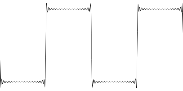
We could produce this type of output by summing sine waves, but back in 2001 the idea of doing this in realtime was laughable. Most of the techniques for producing square waves focus on producing the above output with a reduced computational overhead. In Blargg's method, that means generating an oversampled wavetable of a bandlimited step function, and using this to correct the transitions of a naive square wave when they happen.
For a completely different approach, take a look at how Web Audio solves the problem. Since RAM is cheap, the Blink Web Audio engine generates a whole series of tables, something like three per octave, across the whole frequency range. In each table, it stores a bandlimited waveform, generated by summing sine waves when the oscillator is first initialized. When you request a frequency, it does a linear interpolation between the two nearest tables. The output is almost perfect (only a tiny discontinuity in the amplitudes of the highest harmonic components) and the computational load while running is very low.
But both of these methods have a few problems. One is that the ringing artefacts don't respond well to non-linear processing. For instance, putting the wave through a distortion pedal will clip the overshoot and the aliasing will come back. Another problem is that the locations of the transitions need to be known in advance. The whole idea of the Hard Sync Without Aliasing paper was to play with the phase components in order to squish all of the ringing onto one side of the transition, so that less advanced warning is needed. However, the resulting minBLEP (minimum phase band-limited step) has even larger overshoot.
Taking a step back, if we made our square wave with a physical electrical circuit, and recorded it with a microphone, would there be this kind of waveform captured? The answer is no, because all digital recording devices have filtering on their input to remove frequencies above the Nyquist limit. These filters are analog, as they have to happen before the digitization takes place. Their rolloff is not perfect (because no real filter has a perfectly truncated frequency response) and their effect on the phase components means the resulting waveform has smoothed corners, instead of overshoot. One way to think about this is that perfectly truncating the harmonic content in our square wave generation is like adding a sharp corner to the spectrum. If our time domain looks perfect, the frequency spectrum is compromised. If our frequency domain is perfect, the time domain waveform is compromised.
The best we can hope for is a compromise, with a reasonably good time domain and a reasonably good frequency spectrum to go with it. The answer to our prayers is the polyBLEP.
Polynomial-based Band-limited Step (polyBLEP)
The polyBLEP can be thought of as rounding the corners of our square wave using a polynomial approximation. The most important paper is "Perceptually informed synthesis of bandlimited classical waveforms using integrated polynomial interpolation" from 2012 by Vesa Välimäki and Jussi Pekonen. This is the one that introduced the 2-sample polyBLEP. There are later papers which feature more advanced polynomials, which give an even better sound result, but these are usually given as piecewise polynomials that take a lot more effort to implement. Remember, the compromise is a balance between the following:
- The frequency domain performance (how good it sounds)
- The time domain performance (overshoot etc)
- The computational overhead
- The code complexity
You might dismiss that last point as unimportant, but I'd attribute the popularity of the 2-sample polyBLEP to its ease of use. I've worked my way through the mathematics of it, but that isn't necessary to use it. Most people encounter the following code sample as something you can just copy-and-paste to get decent square and sawtooth waves.
double t = 0.; // 0 <= t < 1
double dt = freq / sample_rate;

...

double poly_blep(double t, double dt)
{
  // 0 <= t < 1
  if (t < dt)
  {
    t /= dt;
    // 2 * (t - t^2/2 - 0.5)
    return t+t - t*t - 1.;
  }

  // -1 < t < 0
  else if (t > 1. - dt)
  {
    t = (t - 1.) / dt;
    // 2 * (t^2/2 + t + 0.5)
    return t*t + t+t + 1.;
  }

  // 0 otherwise
  else
  {
    return 0.;
  }
}

double poly_saw(double t, double dt)
{
  // Correct phase, so it would be in line with sin(2.*M_PI * t)
  t += 0.5;
  if (t >= 1.) t -= 1.;

  double naive_saw = 2.*t - 1.;
  return naive_saw - poly_blep(t, dt);
}

...

for (int i = 0; i < nFrames; ++i)
{
  output[i] = poly_saw(t, dt);
  t += dt;
}
(from this KVR audio forum thread)
The 2-sample polyBLEP is conceptually the result of applying a moving average filter to a perfect step twice. Applying a moving average once would give a straight diagonal line, applying it an infinite number of times would give a gaussian step (the central limit theorem strikes once again). People like polyBLEPs because there's no need for initialization code — the polynomial is a replacement for lookup tables. People especially like the 2-sample polyBLEP because it only has to correct two samples per transition. This has the bonus side effect of eliminating the lookahead problems the minBLEP was attempting to solve.
I've implemented other polyBLEPs, following the descriptions in several papers, of various polynomial orders and samples corrected, but nothing compares to the simplicity and effectiveness of the 2-sample polyBLEP.
With that explained, let's take a look at what is required to implement a 2-sample polyBLEP on the Flash Synth.
polyBLEPS on the Flash
The 2-sample polyBLEP (which I'll just refer to as polyBLEP from here on) is so simple that most people would consider the overhead to be negligible. On the STM32L432 running at 64MHz this isn't the case at all.My first method of profiling an algorithm is to see how many polyphonic notes can be played simultaneously before the buffer underruns. When I ported the polyBLEP code above to the synth, the number of oscillators I could play simultaneously was one. This is before adding envelopes or filters or anything, just straight sawtooth waves, and it couldn't even get to two.
I tried the usual optimisations, putting the polynomial into a lookup table, inlining the function calls, caching the division, and so on, but the best I could get to was five notes simultaneously. Obviously a new approach was needed.
One of the metrics used to evaluate these algorithms is the number of multiply-accumulate operations per sample. Some of the academic papers have tables listing the performance of their BLEPs in these terms. But on microcontrollers like ours, that's actually a really bad metric to go by. The STM32L432KC, like many DSP chips, has a floating point unit (FPU) with a single-cycle multiply. But like most microcontrollers in its class, the code executes directly from Flash memory faster than it can be random-accessed. In our case, it takes about four or five clock cycles to read the flash memory. There is a pipeline of instructions being read, and a branch to a random address has to introduce four or five stall cycles while the pipeline refills.
To put this another way, the cost of a multiply-accumulate is one cycle. The cost of an if condition could be as many as five cycles.
In the polyBLEP saw code above, there are at least three if conditions per sample. For a square wave, which has two transitions per oscillation, there would be five.
With this knowledge in mind, designing a more efficient polyBLEP is easy. The corrections are only applied for two samples around the transition, the rest of the wave is identical to the naive form. There is already one condition per sample that we must keep, which checks if the phase variable has reached the end of the waveform and subtracts a full cycle if so. In the code above, that's double t and these lines:
  t += dt;
  if (t >= 1.) t -= 1.;
For BLEPS via State Machine, I replaced this with a check if the phase var has crossed a threshold. If not, it continues as normal. Else, it applies the correction and chooses a new threshold for when the next event occurs. The code for a polyBLEP saw on the Flash Synth looks like this:
inline float blepSaw(struct oscillator* osc, uint8_t* state, float f, float idt, float incr){

  output +=incr;
  osc->phase +=f;

  if (osc->phase >= threshold) {
    if (*state==0) {
      threshold=8192.0-f;
      *state=1;
      osc->phase-=8192.0;
      output-=2.0;
      return output+1 - bleptable[ (int)((osc->phase)*idt) ];
    } else {
      threshold=8192.0;
      *state=0;
      return output-1 + bleptable[ (int)((8192.0-osc->phase)*idt) ];
    }
  }

  return output;
}
The phases are normalized to 8192.0 for all oscillators, because that's the length of the wavetables in other algorithms. idt is the cached division (256.0/f). For square waves there are four states and a switch statement, but the concept is the same.
For almost every sample, there is only one comparison, putting the overhead of this oscillator only a smidge above that of a naive one. The results are spectacularly fast, and sixteen oscillators at once on the Flash Synth is now effortless.
Limitations and corrections
The first problem with this approach is that changing frequency means the threshold becomes invalid. I only update oscillator frequency every 128 samples, so a simple recalculation of threshold at that point is all that's needed to keep things working.The second limitation is that if the wave period becomes shorter than the number of states it will break. For the square wave, that means a period of four samples, or about 11kHz. That's about MIDI note number E9 in equal temperament, so I don't think it's a concern, and for notes above this I simply mute the oscillator.
The square wave also needs to offer variable duty cycle, which means normalizing the DC offset. Correcting for this makes the code a little harder to follow, but doesn't add any overhead.
Results
The goal was to produce a subtractive synth algorithm something akin to a minimoog. That meant monophonic, with envelopes, filter, filter tracking, modulation and so on. That goal was now easy to achieve.But I also included in the release a mode that had no filter, but maximum polyphony. Aaron asked me why I felt the need to add this given that the filter was never going to be able to run at polyphony of 16 on this microcontroller, and perhaps a reduced polyphony would have been better. I think this is because getting sixteen perfect square waves, in tune, without aliasing, and with full resolution pitch bend, on a powered-by-midi synth, has been a goal of mine for years. I first attempted it here, and eventually managed it five years later. I simply had to share it with the world.
With Aaron's consent, I've finally put the source code to the Flash Synth up on github. You can find the Bleps-via-state-machine code starting at line 1599 of Src/main.c and the two template files named Src/algo3_*.h.