
Better Continuity Test
13 Jun 2015Progress: Complete
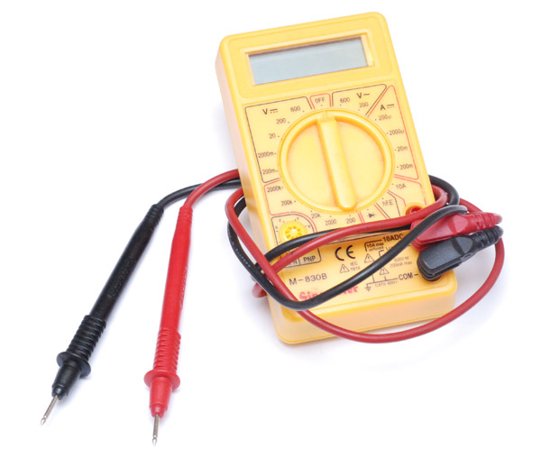
This is my old multimeter. It really is as cheap as they come, and it's served me well for many years.
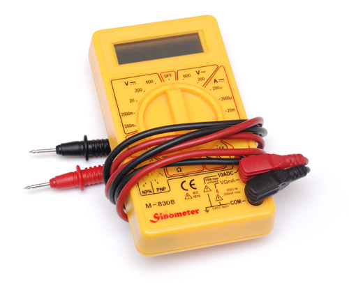
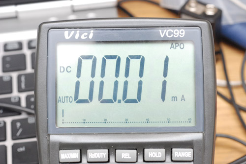
There is one thing it's lacking, you'll notice, and that's an audible continuity check. I guess they saved costs by omitting a buzzer. I thought it was about time I upgraded and after checking a few reviews, ordered a 'Vici VC99' which seemed to have everything I could ever want. There are a bunch of different Chinese multimeters called Vichy and Vicky and Victor, they're all clones of clones. I was horribly disappointed when mine arrived. The review was for a Vici VC97, and on paper the only difference was the VC99 had slightly better range for everything. Turns out the only feature I'd really wanted, the audible continuity check, was unsatisfactory: terrible, terrible lag. It was only updating at the screen refresh rate of ~2Hz and borderline useless.
I want a continuity check that'll squeak if you just barely brush against the correct wire. Not this holding-it-there-for-500ms bullshit.
Other things I didn't like: the VC97 is physically much larger than my old meter, and the auto-ranging can be a bit spastic.
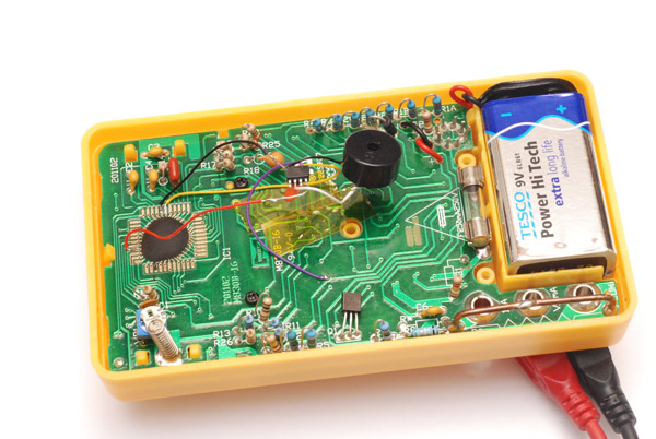
I decided to upgrade the old meter's continuity test. The first step was to tear it apart and try and make sense of the board layout.
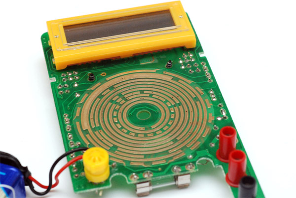
There are six pairs of spring contacts under the dial which connect these traces. After struggling for a while I gave up at this approach and tried scoping the back of it with the dial in place. My idea was to change out the diode checker. The diode checker applies a 2.5V bias, and interestingly, so does the minimum range of the ohmmeter. The rest of the ohmmeter applies about 250mV. Hmmm...
By the way I'm measuring the voltages relative to the probe ground. The battery is floated so that the negative terminal is about -5.5V. After probing the epoxy blob on the back I found a very stable 3V source - there must be a -3V regulator from the positive of the battery. Good, good. It's connected to the ring at the very centre, and is disconnected in the off position.
Next we need to know when the dial uniquely points to the diode checker, which wasn't difficult to trace, but the pin seems to be shared with the lowest ohmmeter. In fact it's shared with the whole ohmmeter, but goes to 2.7V for the lowest and the diode checker, then 300mV for the rest. All other dial positions give 100mV, apart from off which gives zero.
I'd already decided to add a microcontroller to this to do my beeping. Obviously we don't want to risk it getting fried by high voltage at the probe tips so connecting straight to them is out. In fact ideally we want to let the meter do all the biasing for us, and just steal the reading at a faster sample rate. With this in mind, it wasn't long before I found the pin we needed: a very stable 2.400V at the epoxy blob, which drops to zero when the diode checker is shorted. Some further testing confirms this must be going straight to the on-board ADC. That other pin, which turned out to be exactly 2.73V might be a reference voltage, as on the rest of the ohmmeter, where it's at 300mV, the ADC pin goes to 290mV and scales appropriately.
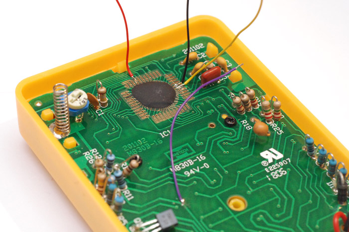
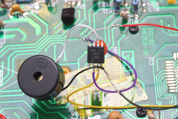
It was pretty fiddly soldering to that tiny via, so I was glad to be able to trace the rest to those handy pads around the chip. You could actually connect a buzzer straight between those pins and it might work. I wasn't sure what effect the power draw would have on the measurement though. One advantage to a microcontroller is you can tri-state the inputs; listening but drawing no current.
Trying to follow all those miniscule vias... boy, I could do with a good continuity checker. Oh wait.
Having spent a good while getting to grips with the workings of the thing, a thought then occurred to me: it's probably more useful to do the continuity checking with a lower bias voltage. Below 0.6V silicon isn't going to conduct, so for checking circuits that'd be far more helpful. It would also mean virtually zero risk of damaging anything. So, the design is decided, let's start coding.
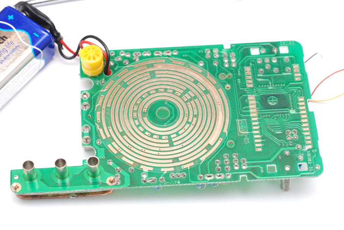
I took the purple and yellow wires to two analogue inputs on an ATTiny85, and sent its timer compare output to a piezo buzzer. We first need to check the purple one and see if it's above 100mV, which means we're on the right dial settings, then read the yellow and send its output to the timer waveform generator. This will give a nice varying pitch based on the resistance. The pitch-to-resistance ratio is of course determined by the dial, as that scales the readings for us.
I figured there was no point sounding on the diode checker/lowest ohmmeter since it's easiest to stick with just one reference voltage. I also pondered upon some activation mechanism for the circuit, maybe a dial combination to turn it on... but nah, let's keep things real simple. The ohmmeter makes a sound. Done.
I left the fuses to their defaults so it runs at 1MHz, and the ADC with maximum prescaling gives a sample rate of about 600Hz, way beyond what's needed.
One final thing is the power consumption. The circuit takes about 0.8mA when the dial is anywhere but off, and peaks at 1.1mA when at its loudest buzz. This might not sound like much but the meter alone takes only 1.3mA - so it's a significant fraction of the battery life we're talking about. The thing to do is put the ATTiny85 to sleep on all the other dial positions. To wake it up, there's no low-level to interrupt from, but we can use the watchdog timer to reset the controller every 500ms. It'll check the dial position and go back to sleep if needed. With this scheme in place, the tiny's current draw when the dial is on the voltmeter or ammmeter drops below the resolution of my VC99. Marvellous.
[Edit: D'oh! Current metering isn't autoranging on the VC99. Still, it's on the order of 10μA.]
I bought some surface-mount ATtiny85s and felt this was a good time to deploy one. The code would easily fit on an ATTiny13, I've ordered some (30p each!) but they haven't arrived yet.
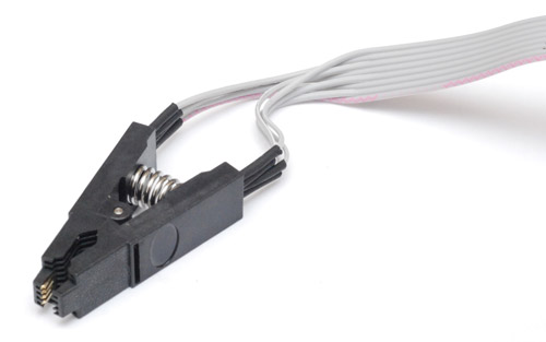
You may wonder how I was able to load the program onto it. The answer is a SOIC test clip, £4 from eBay. Just clip it on and program, very clean.
The 0.1uF cap probably isn't needed but it can't hurt.
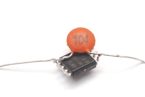
Inevitably, with the chip upside down, I soldered the pins in the wrong order and had to start over.
Looking good now.
And the case pops back on as if nothing has changed.
But it's changed all right. We've now got a brilliantly functioning audible continuity checker!
The case being closed does dampen the sound somewhat, perhaps some holes are needed. I do like the unblemished exterior though, nothing to suggest that this flimsy meter is better functioning than the one that cost ten times as much.
I checked the ohmmeter readings and they all still seem sensible, and did double-check the voltmeter part to make sure there was no chance of burning the chip. All original functionality retained then. Nothing else to say really - a mighty modification indeed.
Here is the assembler source code for your reading pleasure, 100 bytes total.
.include "tn85def.inc"

    ldi r16, 0
    out DDRB,r16
    out PORTB,r16

    ; Timer wavegen setup. Setting OCR1A (pin toggle) to 1
    ; will stop waveform when OCR1C (timer reset) is zero
    ldi r16, (1<<COM1A0|1<<CS11|1<<CS10|1<<CTC1)
    out TCCR1,r16
    ldi r16,1
    out OCR1A,r16
    ldi r16,0
    out OCR1C,r16

    ; Disable digital input
    ldi r16,(1<<ADC0D|1<<ADC1D|1<<ADC2D|1<<ADC3D)
    out DIDR0,r16

    ; Power reduction
    ldi r16,(1<<PRTIM0|1<<PRUSI)
    out PRR, r16

main:
    ldi r16,(1<<REFS1|1<<ADLAR|1<<MUX1|1<<MUX0) ; 1.1V, left adjust, PB3
    out ADMUX,r16
    rcall readADC

    cpi r16,40 ; <170mV
    brcs powerDown

    cpi r16,255 ; >=1.1V
    breq powerDown

    ldi r16, 0b00000010
    out DDRB,r16

    ldi r16,(1<<REFS1|1<<ADLAR|1<<MUX1) ; 1.1V, left adjust, PB4
    out ADMUX,r16
    rcall readADC

    ; 291mV would give a reading of 67.
    ; So 60 is a good threshold for sounding
    ldi r17,60
    sub r17,r16
    brcc soundOn
    ldi r17,0
soundOn:
    out OCR1C,r17

    wdr
    rjmp main


powerDown:
    ldi r16, 0
    out DDRB,r16
    out PORTB,r16

    cbi ADCSRA,ADEN ;Disable ADC

    ; Power reduction
    ldi r16,(1<<PRTIM1|1<<PRTIM0|1<<PRUSI|1<<PRADC)
    out PRR, r16

    ; Reset in ~500ms
    ldi r16,(1<<WDE|1<<WDP2|1<<WDP0)
    out WDTCR,r16

    ; Power down
    ldi r16,(1<<SE|1<<SM1)
    out MCUCR,r16
    sleep
    rjmp 0


readADC:
    ; Enable, Start conversion, clear interrupt, Prescale 128
    ldi r16,(1<<ADEN|1<<ADSC|1<<ADIF|1<<ADPS2|1<<ADPS1|1<<ADPS0)
    out ADCSRA,r16
waitForConversion:
    sbis ADCSRA,ADIF
    rjmp waitForConversion
    in r16,ADCH
    ret