
Badge
8 Dec 2023Progress: Complete
A simple badge with an LED matrix, powered by a RISC-V microcontroller.
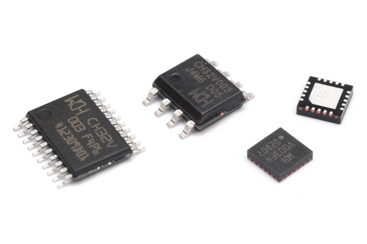
The CH32V003
There's a new chip on the block, named the CH32V003. I'll admit the name is a bit of a mouthful, I've idly been referring to it as "the chirty two" or "the double-oh three" but don't let the unassuming name fool you, this chip is grand.It's a self-contained microcontroller with a 48MHz RISC-V core that costs about $0.15 in single quantities. It may seem odd to dwell on the low price, but throughout the chip shortage I witnessed many of my favourite parts quintuple in price, or become unavailable entirely, so having a new microcontroller that's cheap and available is a big deal.
Since the part is so cheap, I ordered about fifty of them in various packages just to have a play around.
One of the most appealing things about the chip is that CNLohr has created an open source toolchain for it: ch32v003fun. I didn't even bother looking at the official tools, the blurb alone for ch32v003fun had me convinced. It's still a little rough around the edges in places, but it's everything I want from a project like this – it's lean, efficient, and understandable.
To get a feel for the new part I did a few different projects, this badge is one of them.
QFN breakout board
The different packages all contain the same part, there's no variation in memory or peripherals. A 003 is a 003. The most appealing package to me is the 3x3 QFN-20, which was previously my favourite format for ATtiny chips. It's physically tiny, almost as small as a BGA, yet still easy to solder, all pins are visible.One thing to note is that the pin pitch is a slightly unusual 0.4mm. A QFN-20 can have 0.5mm pitch and still keep the 3x3mm outline. I had a breakout board for 0.5mm QFN-20 and was surprised it didn't line up. I can hand-solder to a QFN, but it says a lot about how easy I now find KiCad (and how cheap it is to get boards made in China) that the fastest option was to throw a custom breakout together.
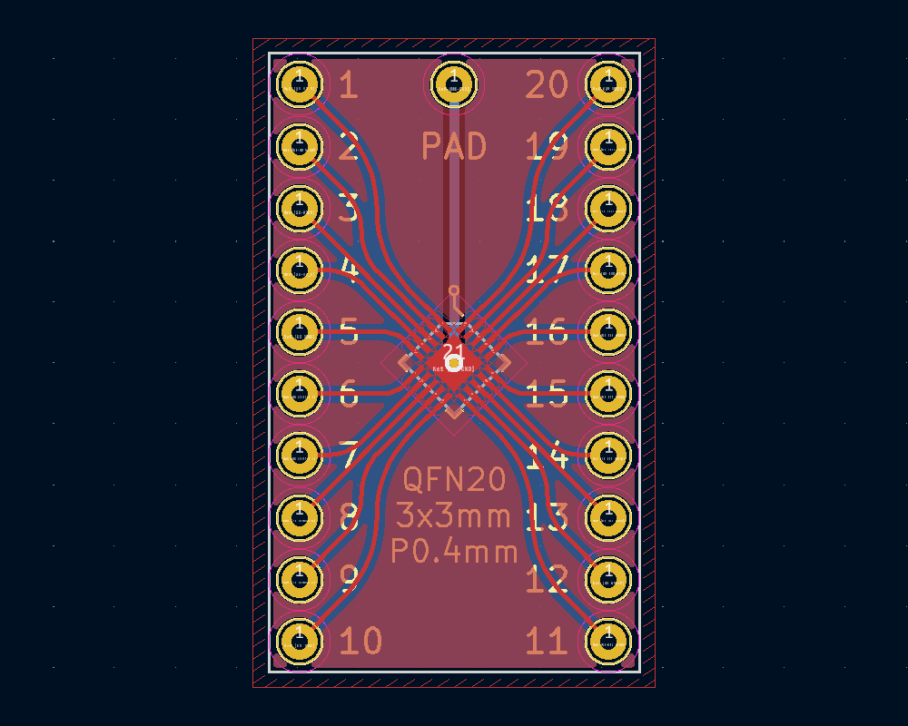
There is absolutely zero benefit in having rounded traces. But it only takes a single click!
Tacked it on to another order as usual, to save on the postage.
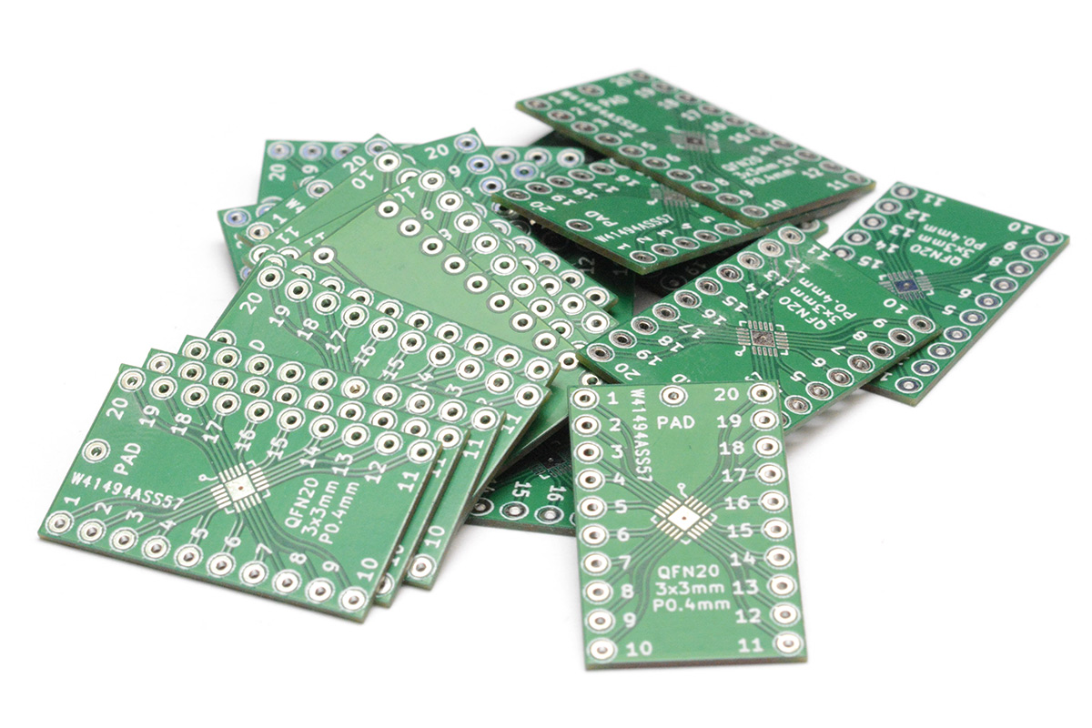
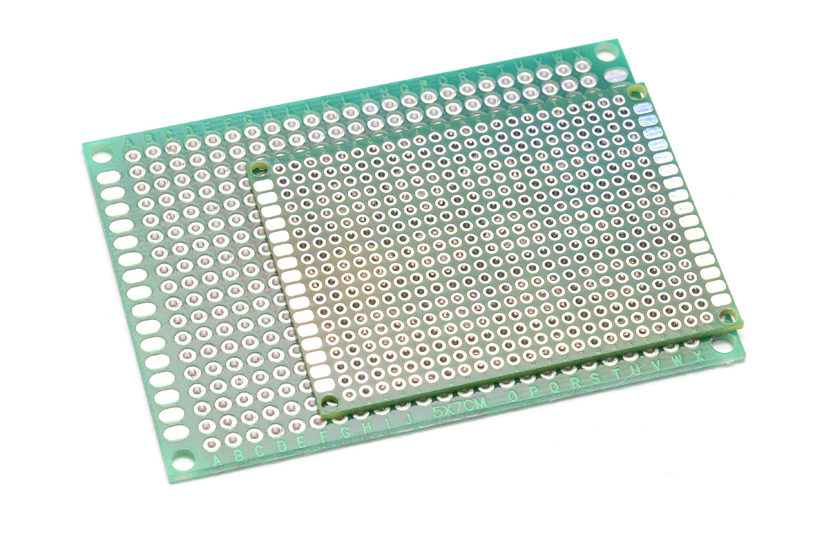
In fact I bunched it together with several other simple boards that in the past I wouldn't have even considered getting custom made. One of these is Metric Protoboard, an idea for which I'd long been yearning. It's like the regular plated protoboard, but the pitch between holes is exactly 2mm instead of 2.54mm – a saving of 27%!
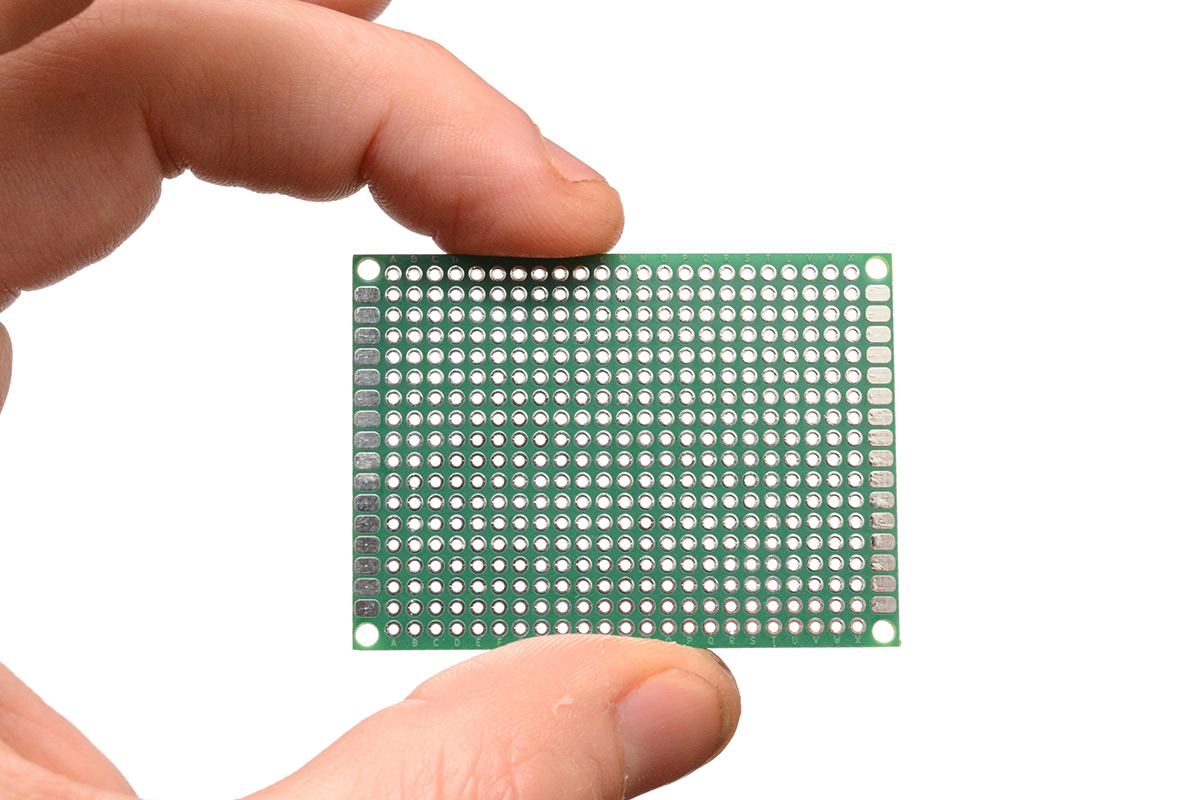
I scaled everything down and even copied the text along the top and bottom. You can get 2mm pitch header pins as well. I'm not sure what I'll do with the metric protoboard, but I know I'll have a use for it at some point.
The Matrix
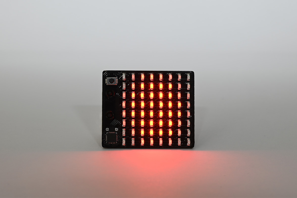
This same PCB order contained those LED matrix boards I used for the volumetric display. I spoke before about how easy it is to assemble these things now that I have a pick-and-place machine. For no reason in particular, I soldered one of them to the breakout board to see if we could light it up.
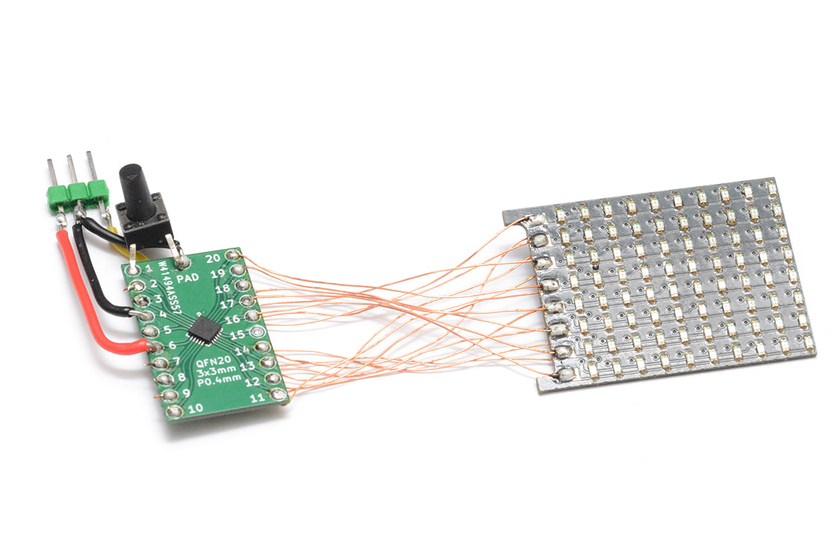
The three header pins at the top are my programming attachment. The CH32V003 has this one-wire debug protocol, so all you need to connect up is power, ground and that one data line. It connects to PD1 on the chip. The push switch is connected to the reset pin, which isn't needed for development at all, I just added that later as a means to cycle through modes.
The LED matrix is 8x10, so we'd need 18 pins to drive it. The chip has 20 pins, two of which are power and ground. It might actually be possible to use all the remaining pins as GPIO, but that means disabling the reset and debug pins. The minichlink utility that comes with ch32v003fun has an "unbrick" mode, which I ended up finding incredibly useful as I mucked about with the chips. I think it just power-cycles the chip and tries to connect before whatever you've done comes into effect.
For the moment though I wired up the matrix as 8x8, so we can easily reprogram it and keep that last pin for a button. We could easily make the matrix twice the size by doubling each LED with complementary polarity. The matrix is driven push-pull, and the LEDs only illuminate in one direction, so each position can be turned into two pixels trivially. However, this little board isn't wired up that way.
Thoughts on the chip
I got going incredibly quickly. This is more a testament to the work CNLohr has put in rather than the chip itself. But my overall feeling is that I really, really like this chip.Naturally we're comparing it to the ATtiny series, and I suppose also the Pico / RP2040 which fills a slightly different category.
Much like the ATtiny, and unlike the Pico, this part will work just fine with no supporting components, not even filter capacitors. It probably works better with capacitors, but it doesn't need them. The RP2040 needs a lot of supporting parts, as it has no onboard flash memory, and if you want to use the USB bootloader then it needs a crystal oscillator, and a switch to put it into boot mode. I've not investigated whether it can cope without capacitors but given you already need to stick it on a circuit board there's no reason you'd not fit them.
The CH32V003 has a 32-bit RISC-V core running at up to 48MHz. This sits it about halfway between the Pico (133MHz dual core) and the 8-bit ATtiny series (up to 20MHz, but one-instruction-per-cycle). It occupies a similar niche, perhaps on the low end, to what the STM32F103 once did (72MHz 32-bit). The manufacturer WCH originally started out making clones of the cheap STM32 parts.
The part has 16kB of flash memory, although that's actually understating it because to my surprise, the bootloader area is also re-writeable. you've got 1920 bytes of flash memory put aside just for the bootloader. The part comes with a system bootloader. I found out that if you wipe this, it doesn't run at all, so evidently there's some setup happening in that bootloader, or perhaps the simplest bootloader would be a jump to the main program. I shall be investigating all of this further.
The CH32V003 can run from 5V. It also has an internal reference voltage so the supply can be measured, and it has a programmable voltage detector I'm yet to play with which is clearly targetting LiPo batteries. When you run it from 3.3V, some of the pins are 5V tolerant. I really like how flexible this is.
About the only area the ATtiny has the chip beat is in power consumption, where during the deepest sleep mode the CH32V003 consumes about 6μA, compared to less than 1μA for the ATtiny. Interestingly, to get into the deepest sleep mode on the chip, you need to enable pull-ups on all the pins beforehand. If you leave the pins floating, the standby current is a few hundred μA.
Video playback
Chronologically, I was working on this a little before building the POV Candle. What we're doing here is superficially similar, exporting a Blender render into a C header file, but without the mental burden of doing it in polar 3D coordinates. However, unlike the candle, I wanted the video playback to have at least some level of greyscale.An 8x8 image with a bit-depth of 1 could be stored in 8 bytes. An 8x8 image with a bit-depth of 8 would be 64 bytes. We have 16kB of memory on the chip, so there isn't a huge amount of space, if we're playing back at 30FPS then about eight seconds of video is the best we could manage, uncompressed, at the full bit-depth.
For this initial experiment, I went with a bit-depth of 4, that should give us a bit more memory to work with, but this comes with a drawback. The effective bit-depth is always going to be less because we need to correct for gamma. The LED visual brightness has a squared relationship with its current flow. It would be possible to do this gamma correction after the data is loaded, but that substantially increases the complexity compared to the basic approach I had in mind.
Instead of PWM for every pixel, we store each frame as (in this case) four separate images. We display the first image for x microseconds, then the second image for 2*x microseconds, the third for 4*x and the fourth for 8*x. The binary combination of these images gives us the 16 levels of brightness with very succinct code. Post gamma-correction it does seem a little quantised, but the resolution is so low it still fits with the aesthetic.
To maximise the length of our video (and keep some memory free for other display modes) I came up with an animation that could be played forwards and backwards repeatedly. It's a triangle that tumbles around, or really, it spins on the spot while the camera spins around it at a slightly different rate.
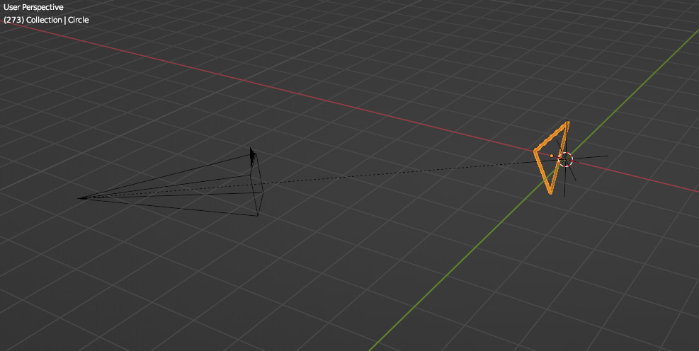
I placed it a little off-centre, so in addition to spinning it wobbles side-to-side.
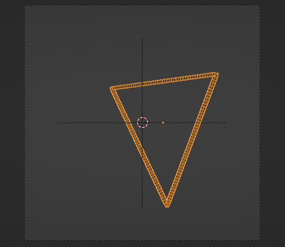
After rendering the frames of the video, a few lines of python turned the PNG sequence into hex values in a C header file.
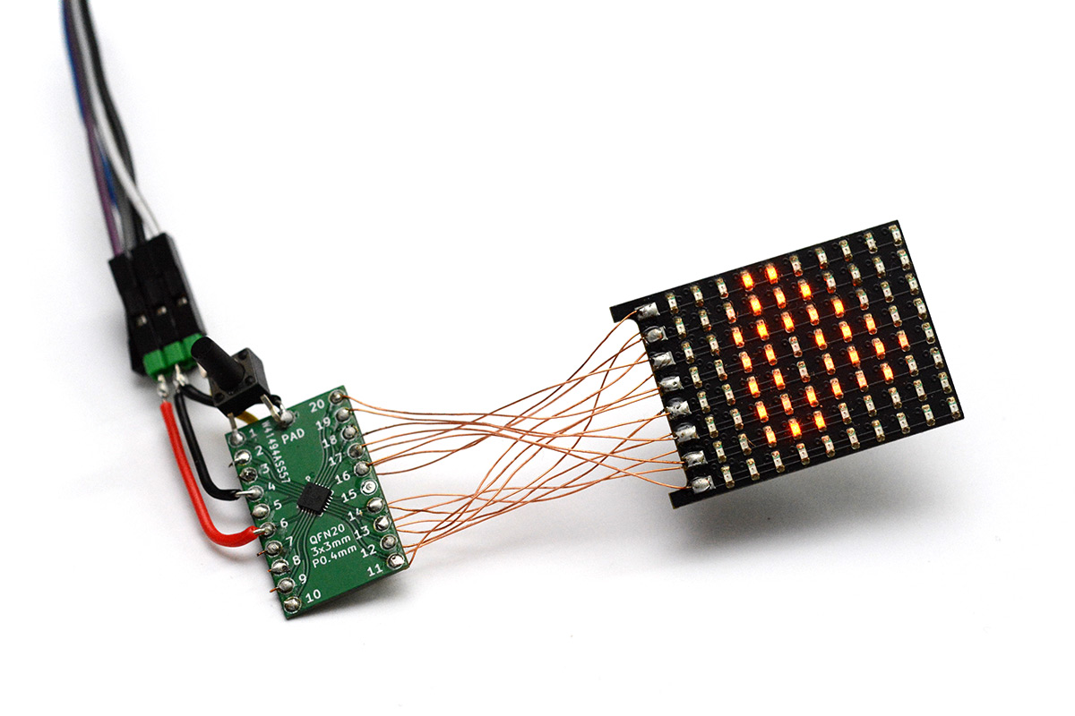
It may not seem particularly impressive, but that triangle is dancing around. I'll make a video of it at some point.
I spent some time tweaking this, getting it to gradually speed up and slow down, making it just interesting enough that you can't spot the point where it loops.
Scrolling text
We can't have an LED matrix and not scroll some text. Step one is converting a font into a useful format, step two is loading the message. I turned to the same font image I've used for years, which I think is originally taken from the Apple II. It's an 8x5 pixel font that's perfectly clear. You can get much smaller fonts but they start to make compromises, like smooshing the details of the letter "m" together.If you're interested in the technical details of loading the font, I'll link to the source code at the end of this page.
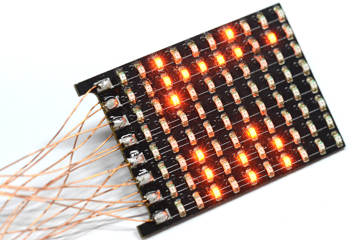
Of relevance to this discussion is the method of cycling through modes. It was at this point I soldered that tactile switch to the board.
You can configure the CH32V003's reset pin to be a GPIO, so perhaps that would be the simplest way of doing this, but instead I opted for having the button fully reset the chip each time, and figure out what to display based on the reset flags. There's a handy register called RCC_RSTSCKR, the reset status and control register, that can tell us the source of a reset. We could use PORRSTF, the power-on flag, but we might as well go with PINRSTF, which flags that the reset pin was activated. These flags have to be cleared manually by writing a one to RMVF but the datasheet is very clear on all this.
More importantly, we need our mode to persist through a reset. The RAM on the chip isn't cleared by hardware, that would be stupid, but gcc will zero any static variables unless we tell it not to. It's a bit clunky, but the proper way to do this is to alter the linker script to create a new section in ram:
  .no_init :
  {
    . = ALIGN(4);
    *(.no_init)
  } > RAM
then declare our mode variable to belong to that section:
uint8_t mode __attribute__ ((section (".no_init")));
Now simply incrementing this variable at the start of our program means it will step through modes every time it's reset. Each mode is in a function that never returns – all is well.
Sleep mode
I wanted one mode to be "off". This means just shut everything down and enter the deepest sleep state. Once again the datasheet is quite comprehensible on the logic to do this. We just set a couple of bits in registers and call the wait-for-interrupt instruction.
  NVIC->SCTLR |= (1<<2); //SLEEPDEEP
  PWR->CTLR &= PWR_CTLR_PDDS;
  asm volatile ("wfi");
Note: the datasheet mostly refers to the interrupt controller as "PFIC" (Programmable Fast Interrupt Controller) although there's at least one reference to it as NVIC. In ch32v003fun they are aliases.
As mentioned above, measuring the current draw in this mode initially came out at something like 280μA. Even though the clock source to the GPIO is stopped during sleep, they retain their configuration from before the sleep was entered. With the GPIO pins floating there's a continuous current drain. Before calling our sleep routine, I set all GPIO to be inputs with pullups enabled, and then the sleep current dropped to about 9μA. It should be possible to chase this further, though my multimeter is so cheap I doubt that figure is at all accurate.
On Badges
As to what to do with this new LED matrix, I had a number of ideas. One of them came to fruition quite quickly and is worthy of its own project page (and video) that'll be posted soon.Another idea which I may yet (but probably won't) pursue is to make some kind of plate mail. The chip is so cheap, and LEDs are also so cheap (I bought a reel of 4000 for $9 including shipping) that we could conceivably build a jacket just covered with LEDs. Addressing them all might be a problem. There's definitely scope for something cool here.
Incidentally, I have a huge amount of respect for Mike Harrison (mikeselectricstuff). I think I've watched almost every one of his videos, so it's a bit surreal when I've met him face-to-face. He handed me one of his badges. I'm not sure if it's published anywhere, but the badge is a very clever construction. It's an array of flashing LEDs. There's no microcontroller, each LED is the self-flashing type. When it's powered on, the flashing begins in phase and gradually drifts out of sync due to manufacturing tolerances and temperature variations, so it slowly becomes chaos. There's a touch sensor that lets you reset them back into phase.
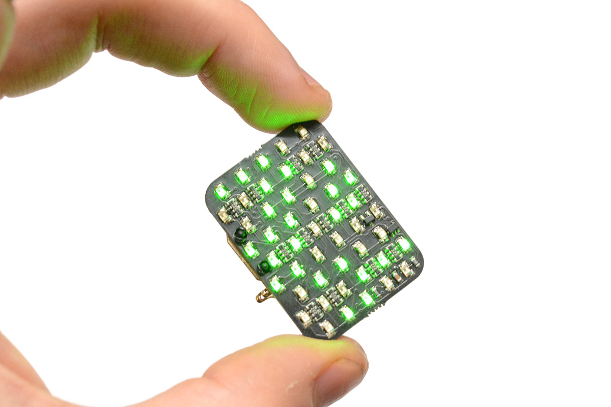
It's a brilliant little thing because it's so simple, and yet it creates quite hypnotising patterns. The flashing lights are enough to impress casual people, but if you understand the electronics you can also appreciate the elegance of the circuit. The only active parts are what looks to me like a regulator and a mosfet. I guess the mosfet is handling the touch-switch aspect. It's powered by a CR2032 coin cell and has a little badge pin attached with plastic rivets.
They say that imitation is the sincerest form of flattery.
Looking at our matrix board, I suddenly spotted the visual similarity between it and Mike's badge. Not everything we do has to be the smallest and best (or smallest and "worst" as is often the case for me). It would be trivial to stick the CH32V003 on a board with the matrix, chuck a CR2032 on the back and call it a badge. Maybe I shall!
Obviously, this doesn't have the elegance of the circuit Mike made, but curiously the processor is so cheap that it might in fact be cheaper to make this into a badge than the array of flashing LEDs.
Will it fit?
I don't want to make the matrix bigger, or change the LED pitch, but holding a coin cell to it shows we probably won't be able to put any other components on the back of this board. I have this battery clip called 3034, which is very slightly narrower than the standard type. Remember this matrix board is 8x10 but we'll only be using 8x8.
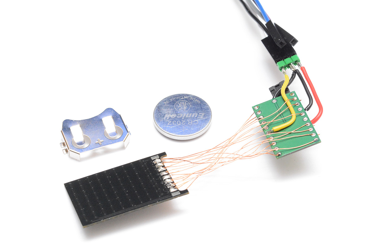
I assumed I could concoct some kind of touch sensor to cycle through modes. Unfortunately I'm not sure I have the board space for it. The annoying thing about the matrix is that, on a two layer board, it takes up most of the routing space. Without some serious reshuffling (this is only a throwaway project anyway) I'm not sure we can fit anything much else onto there.
I added a strip along one edge to hold the processor and the badge pin. I had a good think about whether we could do capsense and concluded not. Mike's badge uses skin resistance to activate the switch, using the very high input impedance of a mosfet (I think). It might be possible to do something similar with a GPIO pin on the chip. The problem is that the internal pullups and pulldowns are all in the region of 50K, which isn't going to work. We could potentially add an external 10M resistor.
One idea that came to me was to use the badge pin as a switch. That's a moving metal part, perhaps we could have the whole pin at one potential, and opening it, touching to the battery clip, would "activate" the switch?
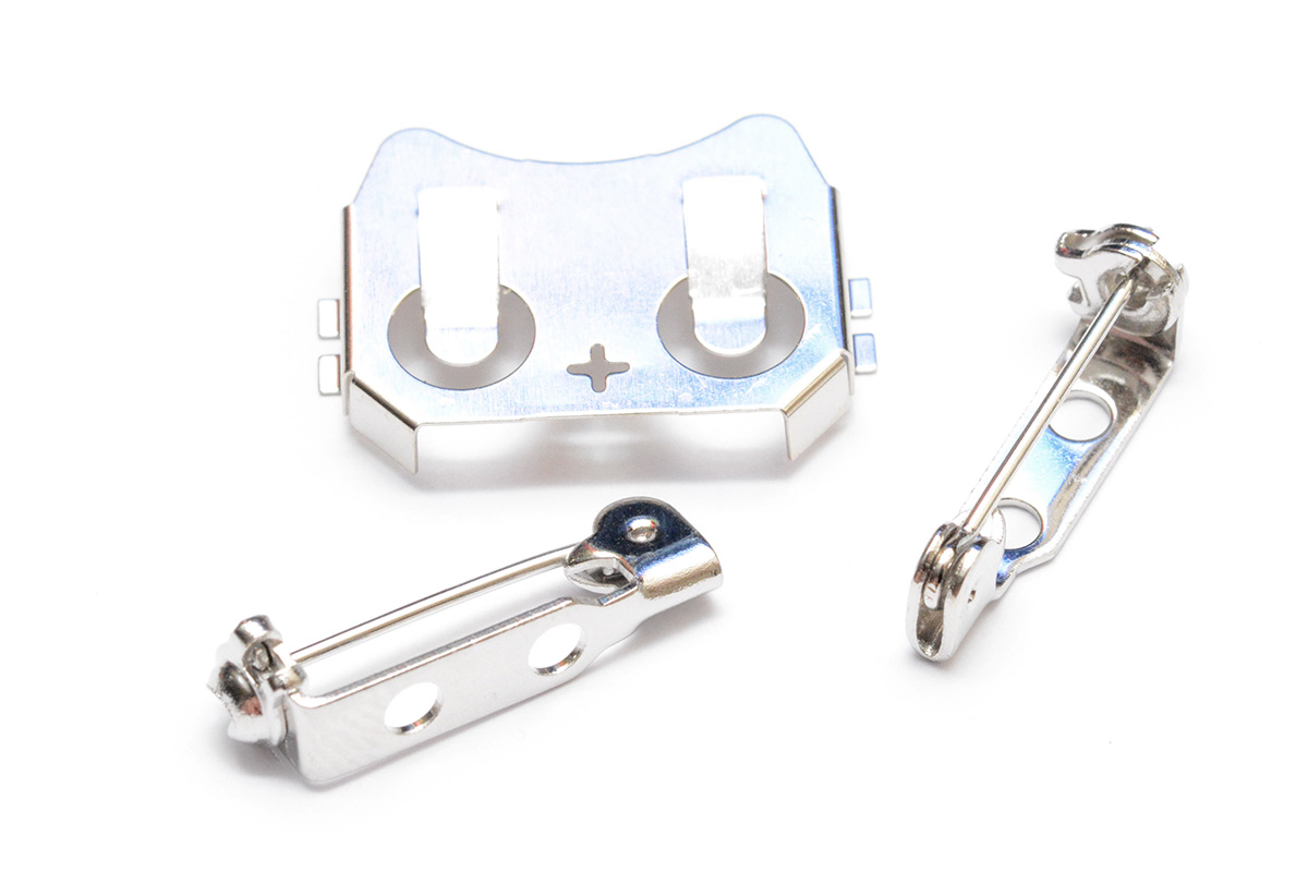
There are a few problems with that idea, mostly that the available terminal of the battery clip is the positive, so we'd specifically need our switch input to be pulled down, ruling out using the reset pin. Also the pin is most likely not going to be pointing at the battery clip, it will be alongside it, or it would be really tricky to use as an actual pin. And finally it would mean you'd have to take the badge off to change modes. Hmm.
It's possible there's a clever thing to do that I missed, but in the name of seeing this project to completion I rolled with a regular tactile switch. This does almost double the bill-of-materials cost, but with some searching I can probably find a cheaper equivalent from aliexpress.
I'm going to flagrantly steal the design of the badge pin attachment, using little plastic rivets. The pin itself I got from eBay, the search terms were "Brooch fastener", "Brooch back", "Badge pin" etc. In KiCad I just added two holes.
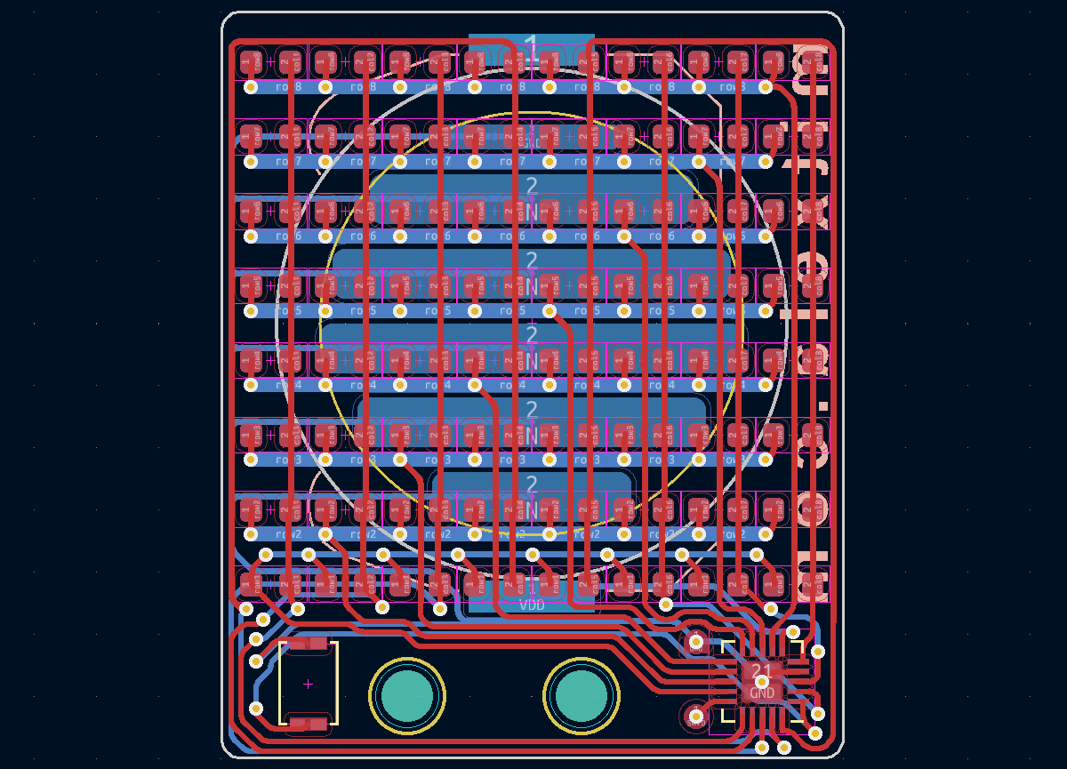
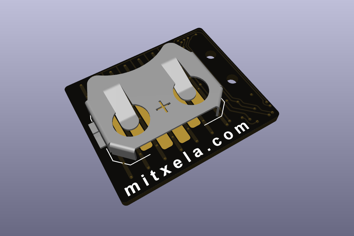
I wanted the routing to steer clear of those holes just in case being crushed by the pin and the plastic rivets caused a problem. Given the required spacing between the pin and the battery clip on the back, I think this is about the smallest possible layout one could do.
Of course the tracks are rounded. Even if they're too small to see.
Under the battery clip I did something unusual, since re-routing the matrix would have been a pain. I left those horizontal traces in place and just made some approximate pads between them for the battery negative terminal. I have a suspicion that this alone wouldn't make contact with the battery, as the solder-resist has a finite thickness, but if the board is manufactured with the cheaper HASL process there should be some thickness to those pads. And if not, it's no cost to add a tiny bit of solder.
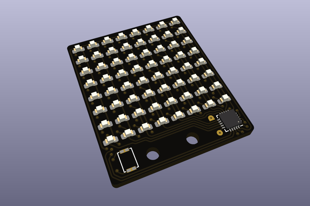
Here's the 3D model:
Sorry I didn't add 3d models for the switch or the pin.
We often forget that it's possible to put anything on a circuit board these days. It's kind of a novelty for me to put my website URL in Arial font. Back in the day, you had to convert it to a bitmap and export it as lots of little squares, it was awful! Not so anymore.
Assembly
At some point, the thrill of getting boards made in China for pennies and assembling them absurdly fast using my own industrial robot will wear off.
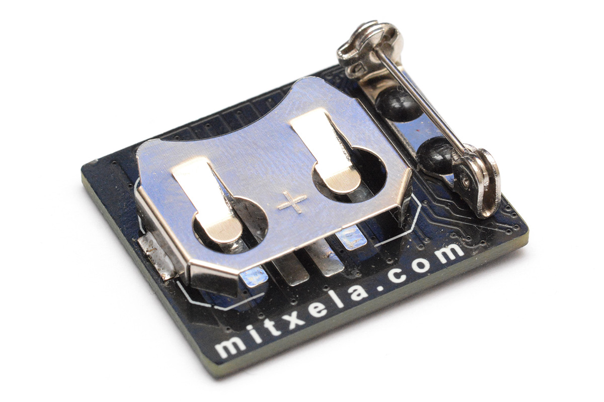
Under the macro lens you can see it's already covered in lint – I couldn't resist taking it to the pub as soon as it was together.
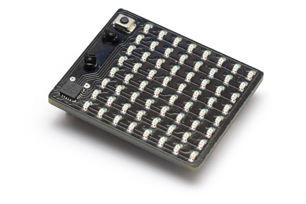
See those two tiny pads near the processor? That's my programming header.

I've done this kind of thing in the past, making very small pads with a plated hole just so that you've got something to grip on. You can take regular pogo pins and shove them, with some encouragement, into female DuPont connectors, making a spring-loaded programming device. But when there's only two pins you need to connect, ground and data, you don't even need the spring pins. It's easy enough to just rest a regular header pin pair against the pads, as in the picture above. Pretty convenient, eh?
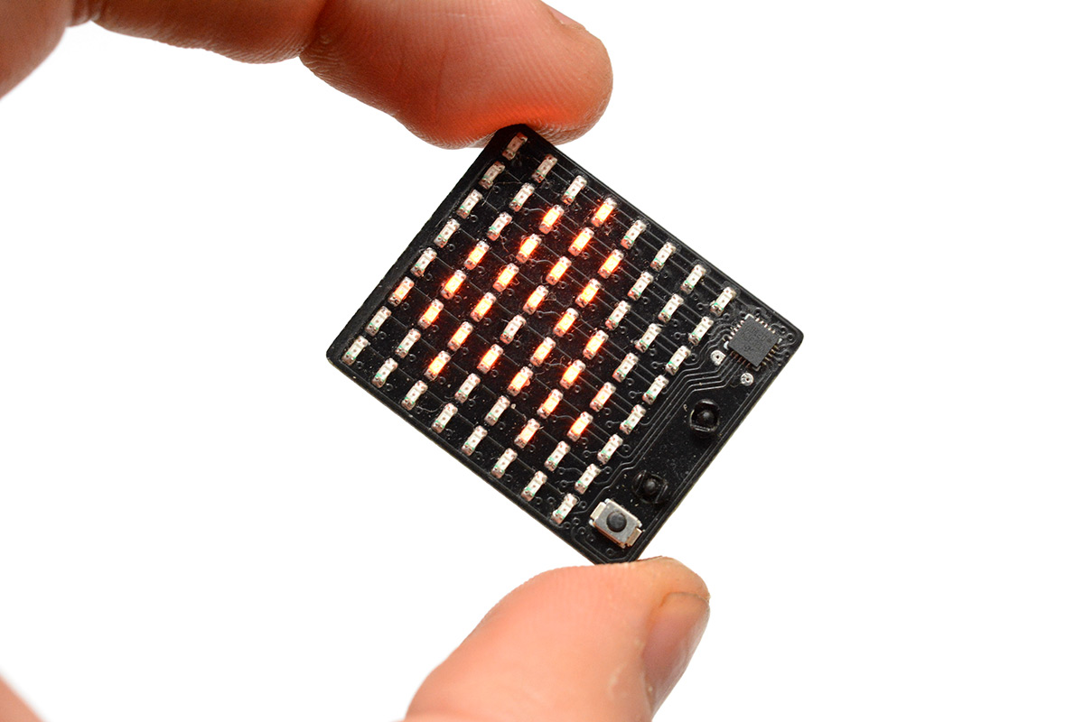
Outside of the brightly lit, perfectly white environment in which I exist, the glow looks quite a bit brighter. That is actually a concern, whether we should intentionally dim the display to maximise battery life. There are a few other places we can squeeze out some better battery life, such as running the processor at a slower clock speed and adjusting the delays to compensate. Those optimisations can wait for the next project though.
Emulating the Blink
If the badge can display video, it can display anything... at least for a few seconds. But there's something much more appealing about showing a pattern that's procedurally generated, that never repeats, that's randomised each time. Sure, we could implement game of life, but even simpler is to lean hard into our flattery and emulate the blinky behaviour of Mike's badge.We can just create 64 timers in memory and give each one a period at which to blink. The systick counter can be used as a random seed. I confirmed that systick is not cleared through a reset, so each time we toggle into this mode it'll show something different. What's more, unlike the analog version, we can randomise the overall period and the spread, so it'll be noticeably different every time.
I guess it wouldn't hurt to make a quick video of the effect.
But remember, it's different each time!
Next
As oddly polished as this badge ended up, it was only meant to be a quick play around with the CH32V003. I feel a strange enthusiasm for the part, a little like when I first discovered the ATtiny series. I've already made two other projects with the chip that need to be written up. I'm producing content much faster than I can document it. But it's really important to record what I can, because I'll forget all the important moments otherwise. The more you learn, the more you forget what you didn't know.Power consumption of the badge is ripe for optimisation. I would also like to look into the voltage detection stuff. It would be great to be able to use a LIR2032 battery with this without worrying, which means undervoltage protection. Another cool thing you can do, if you know the battery voltage, is alter the duty cycle of the LEDs to compensate. This can enforce a constant brightness regardless of battery level.
Source code is on github and git.mitxela.com.