
Automatic LED
5 Feb 2021Progress: Complete
Let me tell you about my dream, of an LED that automatically adjusts its brightness to match the ambient light, without any supporting components...
It's no secret that I've been working on a new and updated version of my Precision Clock (but don't get too excited, it's still months away from release). One of the improvements is to the display, which will read out to the nearest millisecond, and the entire display has been redesigned so that it won't flicker when filmed with a high-speed camera.
As far as I know, there are no off-the-shelf LED display drivers that can meet my specification. Pretty much every driver these days is serially addressed, and even the fastest ones top out at around 50MHz, which isn't fast enough for my needs. There just isn't demand for LED drivers that update with sub-millisecond precision.
I'm not too upset to say goodbye to ready-made display drivers, and eliminating MHz signals can only help our electromagnetic compliance, but this does mean the automatic-brightness circuit of the current generation will no longer work.
Possibly the best bit about the Precision Clock is the automatic brightness circuit. It's an entirely analog affair, with only a few components, and yet it works so perfectly I couldn't possibly improve on it. It works on the full dynamic range from broad daylight to the darkest night, it responds instantly but with a hint of smoothing due to the LDR's response curve, there is no PWM involved, and it's adjustable if needed. It was only possible to create such a circuit because of how LED display drivers accept a reference current.
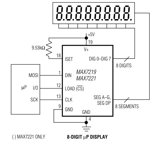
Most display drivers work this way. A pin (usually labelled Iset) accepts a reference current. This is fed, or mirrored, into the driver transistors for each segment, so the transistor gain multiplied by the reference current will set the segment current. The expected use case is to have a resistor set this reference current, and do the display dimming through PWM. Naturally, I was able to abuse this to produce my brightness circuit with only a handful of components.
With discrete components, resistors are cheap and transistors are expensive, but in integrated circuits the reverse is true. Transistors are incredibly cheap and resistors are very difficult to add, especially if you want tight tolerances. In the case of a circuit which needs many pull-up resistors, it's universally implemented as a single resistor to set a reference current, and then transistors everywhere to mirror that current. And, when the resistor needs to be a specific value (with better than 50% tolerance) it's easiest to just expose that on a pin, so an external component can be used, as with the display drivers.
To summarise: the old circuit was awesome, but it won't work with the newer design. We need to come up with something at least as good, if not better.
The situation
For the sake of this page, you only need to know that we're using a mid-range STM32 processor (probably an STM32L476).
After much, much deliberation, the decision was made to run the display matrix directly from pins of the processor. Using the chip's DMA, we can configure a circular buffer that's constantly sent to the GPIO pins, so with a little thinking we can produce a display matrix with no processor overhead.
About DMA
Direct Memory Access (DMA) is a tool to copy data from one place to another. It was invented so that when you need to move data around, the CPU can go off and do other things instead of sitting in a long loop moving data a chunk at a time. DMA isn't necessarily faster – in fact, it's probably slower because the CPU has higher priority on the data buses – but it makes an enormous difference to the overall effectiveness of a computer.Modern DMA systems are so complicated that it can be hard to wrap your head around, but with STM32 it's mostly still manageable. In circular mode, when it reaches the end of the data it will start again from the beginning, so here we can set the matrix values in memory and have them pipe continuously to the GPIO port. The matrix will continue to run, and we only need to touch the data when the display needs updating.
The pins of the microcontroller are not strong enough to drive the full display, which might draw upwards of 300mA at full brightness.
Given the number of segments, any solution that involves discrete transistors per segment is impractical. There are darlington-array chips which may be usable to produce an array of constant-current segments, but in the end I decided to use regular buffer chips (i.e. 74HC244 style) and have plain old current-limiting resistors on each pin.
The first clever bit is that we can now dim the display by changing the power supply voltage of the buffer chips.
Dimming by voltage is not going to be linear, but we can compensate for that. There are buffer chips that work from 1.8V to 3.6V, which is easily enough range to drive the segments from minimum to maximum current.
We can give these buffer chips their own voltage regulator of the adjustable type, and splicing another resistor into the feedback loop we can control the voltage from the main processor's DAC.
Perfect. All we need to do is stick a light sensor on the board, glue things together with DMA and we've got ourselves a fully automatic brightness display.
However. I didn't just want to match the previous behaviour, I wanted to improve on it. And one of the only complaints I could have about the old circuit is that the light sensor is on the back of the clock. This really doesn't matter much because it's such an omni-directional thing, but wouldn't it be better if it faced forwards?
The proposition
As I pondered ways of mounting a light sensor on the front of the clock, it occurred to me there are already light sensors on the front of the clock.Every 7-segment display has a decimal point, but most of these are not used.
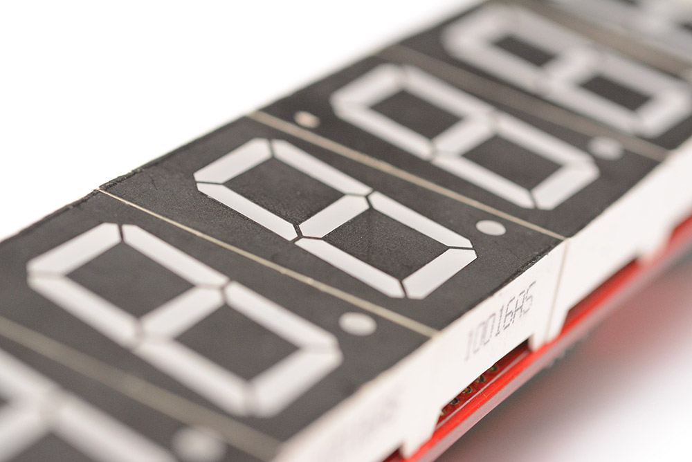
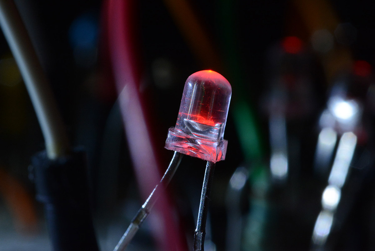
It's no secret that in a pinch, an LED can be used as a light sensor. Could we use those unused decimal points to detect light?
Connecting a multimeter to the pins of a decimal point and shining a torch on the display gave some very promising results.
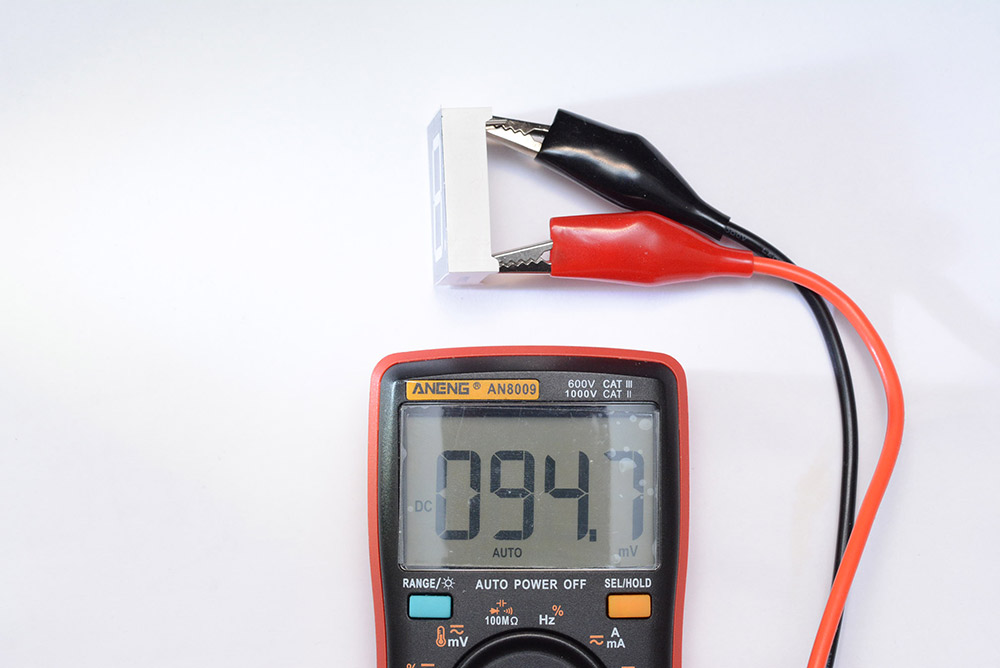
However, the 7-segment displays are wired common-cathode, which is normally very convenient, but in this case makes reading the light level with the unused decimal point quite tricky once the display is turned on. The matrix means the cathode must be alternately pulled low and high. It would be possible to have an open-drain arrangement, where it goes high impedance when the digit is off, but the buffer chips we chose earlier are push-pull.
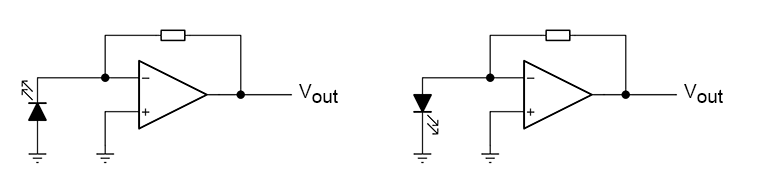
Let's talk about how to measure the light levels with an LED. There are a few ways, the simplest being to just measure the open-circuit voltage on it. What's happening is the incoming light is generating a current, with the number of electrons directly proportional to the amount of light. The PN junction has capacitance, and this photocurrent builds up charge on the capacitor, until an equilibrium is reached with the leakage current.
The multimeter's 1MΩ input impedance can significantly affect the voltage. What's more, the equilibrium voltage has a very nonlinear relationship with the incoming light.
A much better idea is to use a transimpedance amplifier, which directly measures the photocurrent, and so the output voltage is directly proportional to the light levels.
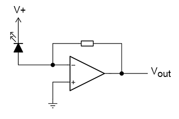
There are a few ways of wiring this up – it's common to reverse-bias the diode, which increases the width of the depletion region and so lowers the capacitance, but that's not needed if you don't care about high-frequency performance.
However, that capacitance turned out to be a killer for this decimal-point idea. I'd thought it would be possible to sample the transimpedance amplifier at the right point in the matrix so that the bias voltage is consistent for each reading, but it became apparent that this just wasn't going to work at the display frequencies we're expecting. Additionally, the diffusion material over the decimal point absorbs a lot of light. I'd hoped that we could overcome this by wiring all of the decimal points in parallel, averaging them out, but doing so also adds to the total capacitance.
After a good while of trying to get this to work, it was time for a rethink.
The better proposition
The attenuating diffusion material, and the fact the LEDs are wired in with the rest of the high-speed matrix, are what killed the first idea. However, there are other LEDs on the clock, which have no diffusion material and don't need to be wired in with the regular matrix: the colon separator LEDs.
The difference here is that these LEDs need to light up, which brings in a whole different class of problems, but I'm sure we can work around it.
We can build a custom circuit to drive these LEDs, one that perhaps will let us PWM their brightness. In the 'off' moments of the PWM signal, that's when we can sample the light levels.
After many iterations, I came up with a circuit that looked like this.
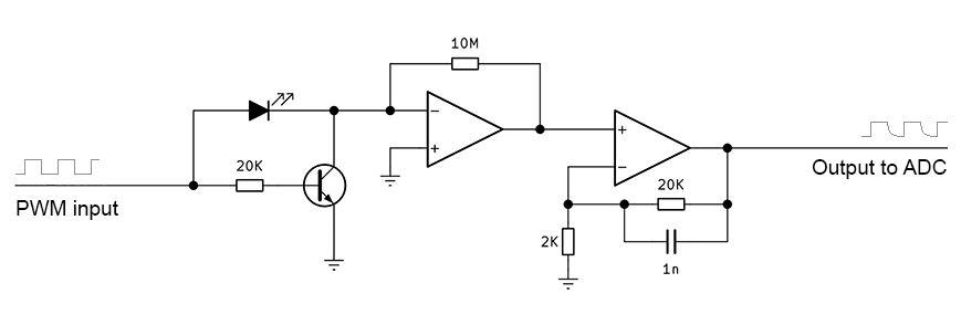
The first amplifier is configured as a transimpedance amplifier, and the second stage is just to boost the signal a bit. The processor's PWM signal is driven push-pull, and goes to both the LED and the (current limited) base of the NPN transistor. When the PWM signal is high, it both sources current for the LED's anode and activates transistor, making it light up. When the PWM is low, the transistor is off, and the anode now is effectively at ground potential.
One of the confusing things about the transimpedance amplifier is that it doesn't really matter which way round your current source is. If you're not reverse-biasing it, only connecting it to ground, then turning the LED around will simply invert your output signal. However, we need to worry further if the op-amps are single-supply. Naturally, a low-voltage rail-to-rail op-amp is preferable since generating negative voltages is extra effort. But if the op-amp cannot produce a negative voltage, then we need to be careful to keep the signals positive.
In my circuit, the choice was deliberately made to produce a positive signal at the intermediate stage, and have a non-inverting second stage. The non-inverting input of the first amp is connected to ground, but it could instead be connected to a reference voltage somewhere between the supply rails, which would add a bit of a safety margin to the signal.
We can boost the signal by wiring all four LEDs in parallel. So long as they're from the same batch, it should be fine to do this.
Our maximum PWM rate is limited by the capacitance. When the signal turns low, the excited LED will slowly decay to a value proportional to the ambient light. It turns out that not just the final value is proportional to the light level, but the speed of the decay is proportional too. In effect, we don't need to wait for it to settle fully – we can simply sample it after a fixed period of time.
Here's some shaky phone-camera footage of the effect:
PWM frequency here was 1kHz. While that's a lot slower than the main display needs to run, it's acceptable for the colons to be driven at that speed.
The component values were chosen after much trial and error. I may not have made clear the dynamic range we're working with here: there are about 16 EV stops between a sunny outdoor scene and a candlelit dinner. That means there's around 32,000 times as much light in the first scene vs the second, or about 45dB.
One method of improving our dynamic range would be to apply a logarithmic gain curve with the second op-amp. This is tricky with our low-voltage rail-to-rail op-amps, but will probably be necessary if we want to extend to the full dynamic range. The microcontroller's ADC is 10-bit, so a logarithmic gain curve would overcome the low bit-depth. Before we fiddle further though, I wanted to see if this system could be implemented without adding enormous overhead to the processor.
Automation
There's something very satisfying about making use of almost everything available to you on a microcontroller. Often, the chips are packed with features and mostly you'll only use a handful of them at any one time. But occasionally you'll find an application where a microchip fits perfectly and all of the peripherals must be used at once.The mid-range STM32 chips offer an awful lot of DMA channels, and at this point in the design of the clock I was already using many of them. The display uses multiple channels, because multiple GPIO ports are used for the full matrix. The USB transactions and the QSPI flash memory use it as needed. The UART makes especially good use of DMA, since the better STM32 chips have a "character match" interrupt (CMIE). This lets you trigger an interrupt on a line-ending, and reset the DMA to read in the next line each time. The processor is only bothered when data has arrived and is ready to process, never otherwise. It's quite satisfying.
Our PWM is generated by a timer. At a certain phase of the PWM waveform, we want to sample the ADC voltage. The ADC reading then needs to be dumped into memory, and after a certain number of readings we can take an average and send the result to the DAC.
The DMA channels are all quite particular, and only certain timers and peripherals can be used with each one. I had to reshuffle things so that Timer 2 was freed up and reassigned to produce the PWM. The timer has multiple channels, one of which controls the PWM duty. The other channel, while clocked and reset from the same timer, is set to a different compare-match value. The ADC is configured to trigger from this compare-match event, and separately, a DMA channel is configured to dump ADC values into memory. In the DMA interrupts, we can average the readings and send brightness values to the DAC.
If the PWM frequency is 1kHz and we want to average a hundred measurements, that would put our display brightness at an update rate of 10Hz. That might not sound too bad, but it looks noticeably jerky when light levels change. Instead, we can set up another timer and another DMA channel to send values to the DAC. At the half-transfer and transfer-complete interrupts, we can take the last handful of measurements, work out the new brightness value, and generate a smooth curve of samples to send to the DAC. If needed, we could average a full second of data, and only interrupt once per second, an almost negligible amount of overhead. The result is very smooth, although the delay is noticeable in that case.
So after a comical amount of setup, we now have an automatic brightness adjustment with no processor overhead, detecting ambient light levels using an LED that forms part of the display.
Changing the PWM duty does affect the reading slightly, so some compensation is required. Small duty cycles don't fully excite the LED, so the sensitivity drops. However, on my breadboard, this system seemed very promising.
The STM32L476 even has, as peripherals, op-amps for general use. Uncomfortably efficient!
Conclusion
Despite how clever, efficient and satisfying this design is, in the end I decided not to use it.I built a prototype clock with this brightness circuit, and just couldn't convince myself that it was good enough.
It's not the dynamic range, we could expand that. It's not the sensitivity, that's acceptable. The problem which makes the entire thing unusable is that the LEDs are too directional. Even after sanding the top of the LED casings, I found it to have a very narrow cone of vision. This means that tilting the clock upwards can send it to full brightness, while the shadow of your face on the clock can send it to the lowest brightness. The LDR used by the earlier clocks is very omnidirectional, so much so that waving your hand over the sensor has almost no effect.
One way of saving the design would be to add more LEDs, on the back of the clock, pointing in different directions. The average of their readings would maybe suffice. But if we're going to add more sensors on the back, we might as well make them proper photodiodes instead, making the clever LED-as-light-sensor setup somewhat pointless.
My insistence that every single aspect of the newer clock needs to be the same or better than before means it's going to be a long time before the new model is finished. However, when I do finish, it's gonna be the greatest wall clock in the world!