
A Silent PC
27 May 2009Progress: Completed
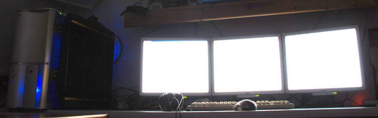
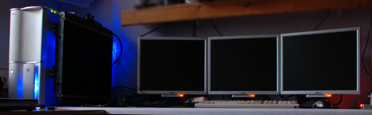
The challenge: to create a silent PC.
After upgrading both my graphics cards, the noise my PC was making was terrible. I decided to modify the cooling system so that it wouldn’t keep everyone awake when I left it on overnight. Also, my budget would be as close to zero as possible. And, the result has to look good. And be fast.
The main parts that need cooling are:
The CPU
The 2 GPUs
The northbridge
The PSU
Also of concern (but simply needing light airflow, I judged) are the hard drives and RAM.
The options
Of the hundreds of ideas I came up with, these were my main options:
Air cool it – ducted.
Upgrade the heatsinks to bigger, better, passive ones. Build ducts around the case to route air flow, and undervolt all the fans to keep the noise down. Here's a nice example
I considered this the best option for a while, since it seemed to be easiest, cheapest, and most practical. However once I started working things out, it got more and more complicated. I got hold of some scrap heatsinks to use, but they were all about the same size as the current CPU heatsink, and too tall to use for the GPUs. I decided to cut them down, but after a while it became obvious this wasn’t going to work, and thought I could build new ones out of sheet aluminium.
I found a site which gave details on building heatsinks for audio amps. These seemed great, and I could build them to fit the spaces perfectly. However, checking the cost of 2mm aluminium, I didn’t think it’d be a cost effective choice.
Peltier Cool it (thermoelectric effect)
I looked into a couple of exotic cooling systems, even compression cycles (as in, a fridge). The main problems are the cost of running them, as they’re very power hungry, and also the fact that the system will be cooled to below ambient. This means moisture will condense on the components, leading to all kinds of problems over a long period of time. For that reason I decided to gives these ideas a miss.
Air cool it – passive.
Heatpipes can work wonders, and if I routed the heat to large enough heatsinks, there would be no need for fans at all, like this build. I found a few places people had done this, and while they worked well, there were a few problems: convenience was sacrificed, as the pipes needed to be as short as possible this meant routing them in awkward ways, which would make it hard to upgrade; and cost. The easiest source of heatpipes is salvaging them from expensive heatsinks, which is out of my range, considering the number of parts I need to cool.
Oil cool it
Systems like this are brilliant, but messy. It seems to work well, and cheaply, but if anything needs upgrading I can’t imagine it being easy. Plus, it would take up a lot of space on my desk. It’s a pretty underdeveloped field, and the possibilities are huge, but I just can’t see it being that practical.
Watercool it.
At first I dismissed this as out of my budget, but the possibilities within watercooling were so great I just had to think some ideas through.
My mindset was this: if a cooling system is vastly more powerful than needed, then I can run it at a fraction of its capacity and the noise will be negligible.
There are many factors determining the cooling power of any system. The equilibrium point depends on the mass of coolant/heatsink and its specific heat capacity, and the rate at which heat is dissipated overall. The cooling power depends on the ambient air temperature, because that is where the heat will end up, except for some of the more exotic designs. The bigger the temperature difference, the more cooling power we have available. The equilibrium point is the asymptote which arises from these two factors.
What we’re concerned with is a) the position of the equilibrium point, and b) the time taken to reach the equilibrium point. If it’s several days, then the position is less important, as it’s unlikely the computer will be under full load for that length of time. This is one of the reasons I chose not to do the oil cooled idea. The heat capacity is tremendous, and so it takes many hours to get up to temperature, but the equilibrium point is much higher than I’d be happy with, as the cooling power of a fish tank is quite small, with such a small surface area. The ultimate system then is a watercooling-designed radiator connected to a submerged (oil cooled) setup, meaning excellent transfer of heat to the coolant, excellent transfer of heat to the radiator (although any electrically non-conductive fluid will be compromising in heat conduction), and excellent transfer from the radiator to the air.
It was not until I started finding sites where people were crafting their own waterblocks that I became convinced that a watercooled rig would be within my budget. If I could craft every part out of scrap metal, the cost should come down tremendously. I looked at hundreds of sites with DIY projects of all kinds, and decided once I’d built my waterblocks, there would still be many decisions to make. The number of different watercooling rigs out there is incredible, as it’s such a flexible cooling system.
Understand the concept of watercooling first, though. Many sites I visited began with the line “The specific heat capacity of water is almost 1000 times that of air” which, while true, does not mean that watercooling is 1000 times better at dissipating heat! This would only be in an open system where the water is never recycled. Every watercooling system I’ve seen is closed-cycle. No, a watercooled system is not a new way of dissipating heat – in almost all cases the heat is dissipated to the air eventually, just the fluid is used as a means of transporting heat. Unlike heatpipes, there’s no phase change, but unlike heatpipes also, the water can be driven by a pump, vastly increasing performance. Convection watercooled PCs do exist, but for all the effort needed, heatpipes are better. Essentially we have a heat source, a fluid to conduct it, and a radiator to dissipate it. 99% of watercooled systems are just that – and the radiator is placed inside the case, usually at the front, and actively cooled (by fans). The benefits of this are purely so that you can dissipate the heat away from the main circuitry. The radiator usually isn’t much bigger than a normal heatsink. Often people use intercoolers from cars as the radiator, they’re pretty ideal for this.
Zalman sell a “Reserator” passive radiator that sits apart from the PC. It costs a bomb, but claims to cool the pc silently. It looks nice, but it’s a rip off. Also, quite inconvenient I’d imagine. Some DIY setups had used entire car radiators, which seemed like a good idea. A huge radiator like that could dissipate heat so well it might work passively. Most of these systems looked very, very messy, as old car radiators always will be. Another problem is fin density. A wall radiator in a house has probably one fin per inch. A car radiator will have twenty or so. The reason is that a car radiator is of the same design as a CPU heatsink, but bigger – not scaled up, but just more of the same. Car radiators are designed to be run with huge air flow, not passively, which hampers performance for a PC.
There are more ideas though. One is to locate the radiator outside the PC, and even quite a distance away. Putting it outside is a good idea if you live in a cold place (which I do, to an extent) but then you’ve got to protect it from the elements. I also live by a river, and using running water to cool the PC would be *extremely* effective. It’s not as simple as diverting flow though – because the stream water is dirty, it’d have to be kept far away from delicate parts, specifically those that would corrode. The best thing would be to have a watercooled setup with the radiator placed in the stream, so the two water bodies remain apart from each other. The logistics of building this though are out of my reach, it’d be expensive to have such a long hose, and such a powerful pump to get it to my upstairs room, and also it’d be pretty much permanent if I ever want to move the PC.
Another method is evaporative cooling. This is a closed system, but with a cooling tower like a power plant, which sprays the water through air flow to evaporate some of it, cooling the remaining liquid. The main problem with this is that it’s noisy. Also, you need to top the water up as it runs out over time, which would be expensive if I were using non-conductive fluid. And, it’s very bulky, and overall impractical in my view.
I thought out many more ideas, but in the end I decided I would watercool the PC, with a modified car radiator attached to the side. And so, I began...
Construction
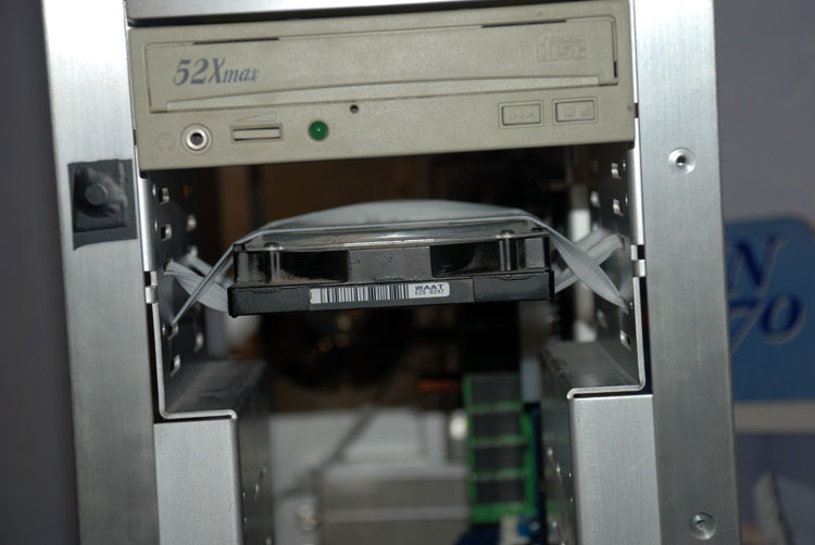
The Hard drive
...is easier to silence than you may have thought. Suspending it from elastic is incredibly effective at getting rid of all the hums and whines it makes. The ticks are still audible, but they can be drowned out by foam around the case.
The waterblocks
These are without question essential to get right. The number of designs out there baffles the mind, with all kinds of different theories supporting them. The aim of course is to transfer the heat of the processors into the working fluid. In a car engine the waterblock is built into the engine block, but with processors this isn’t possible at all. It has to be removeable, and not get the processor wet. Many early designs were milled out of copper blocks and involved simple swirls or fins, and worked fair enough, but later designs show that the best idea is to create turbulence within the water. A modern system will have a powerful pump, going through very dense fins, with a lot of resistance. This may be the ideal waterblock, but buying brand new can mean huge amounts of money. You can pay hundreds for a single waterblock, and I would need at least three, for the three main processors. A homemade design can’t really compete with top end waterblocks, but it can come close.
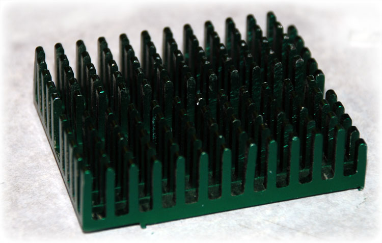
To begin with, the CPU. My design was to combine a swirling effect with the turbulence of cooling fins. I began by taking a heatsink I’d found on a Pentium I processor, as it was about the right size.
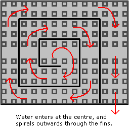
I filed down the paintwork as much as I could and then from a single piece of aluminium strip, made my guide piece. This took far more planning, effort and frustration than the pictures can really convey. Here’s the basic flow route:
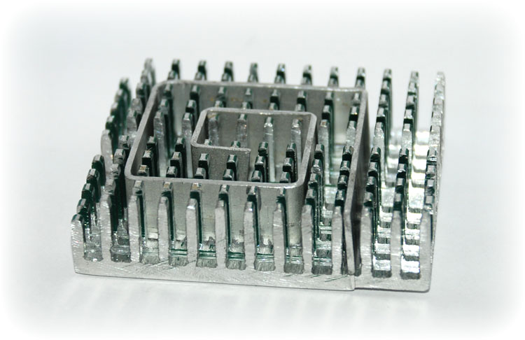
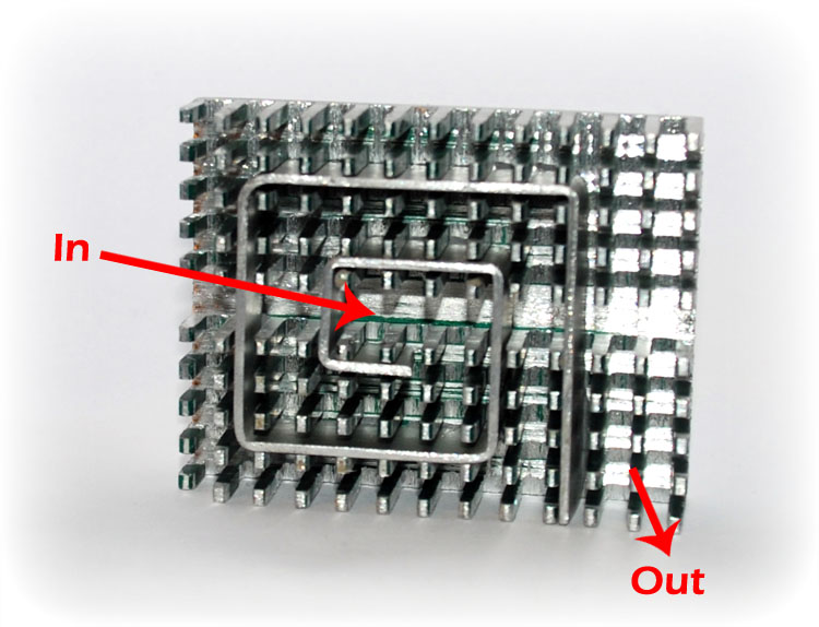
I joined it on using everyone’s favourite cold weld epoxy, JB weld. To finish I covered it with a tiny piece of sheet aluminium which I’d recycled from a tray I found in the kitchen. I then plastered all the joints in more cold weld to make it watertight, hoping there were as few internal leaks around the guide as possible.
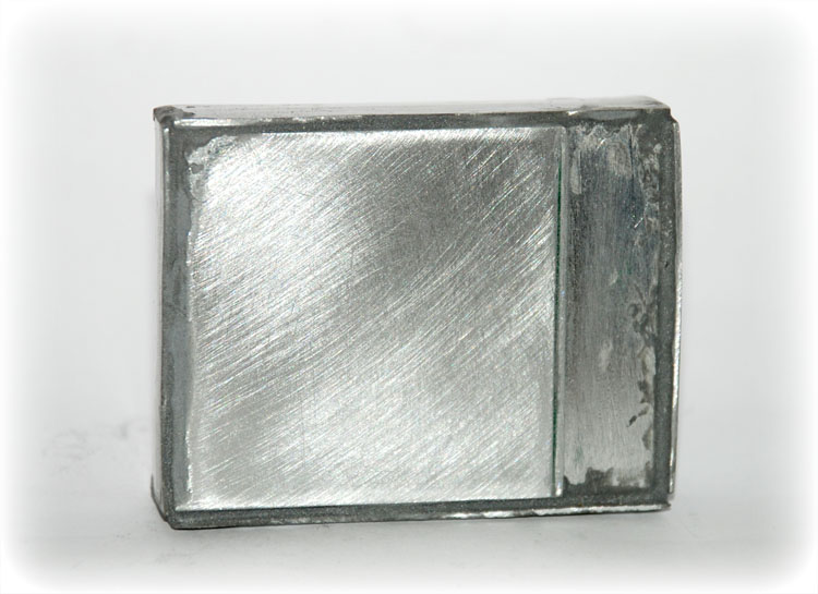
The underside I polished to as close to a mirror finish as I could manage.
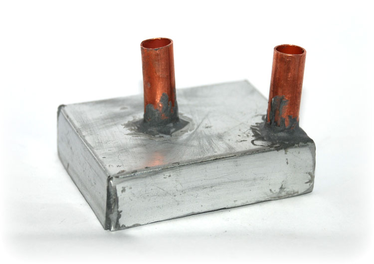
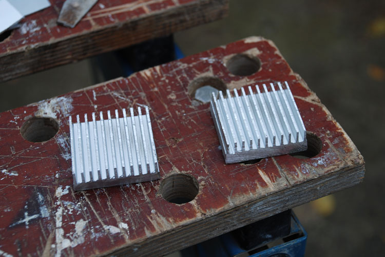
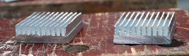
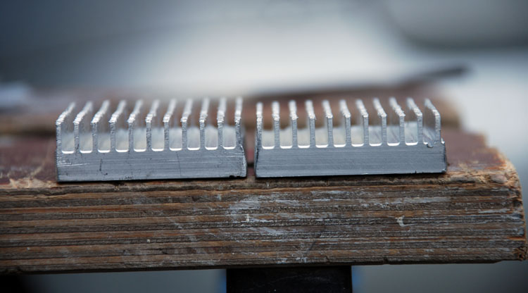
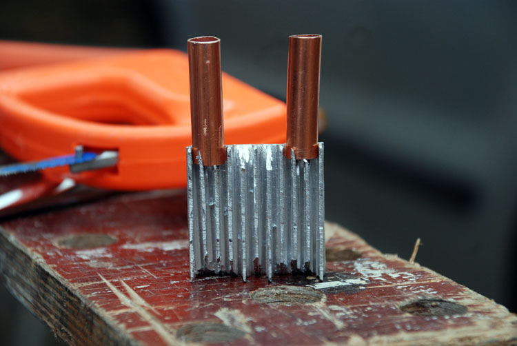
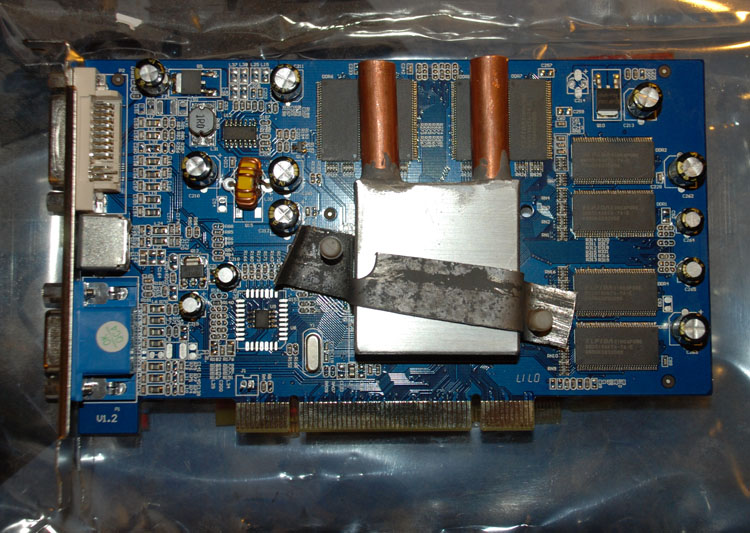
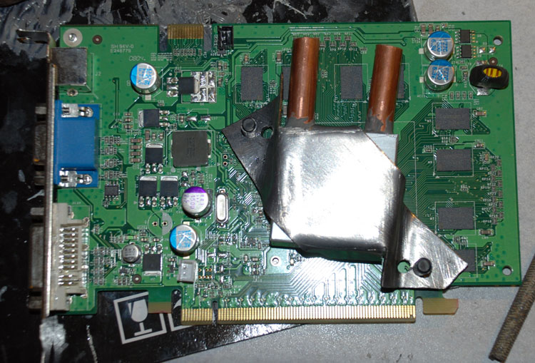
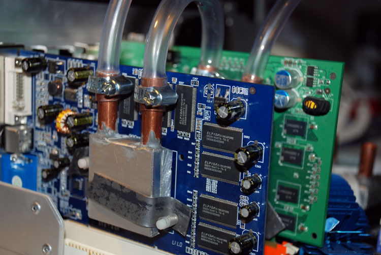
The GPU waterblocks were made from one heatsink I sawed in half.
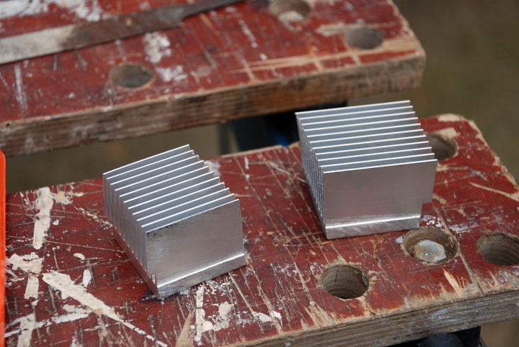
I cut them down a lot. I wanted their form factor to be small enough that I could still use the remaining PCI slots. If it’s possible on commercial waterblocks, it should be possible for me.
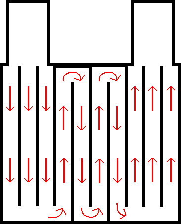
Next I needed to route the water. A swirl would be out of the question, since the ports were both coming out of the very top. I decided to go for a down-up-down-up-down-up design. Alternating fins would have notches cut in them at the ends, with the outer three channels merging and going to the pipes. It looked messy, but it hopefully should work quite well. This diagram from trusty MSPaint should explain it for you:
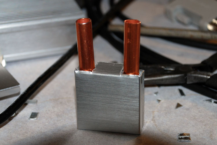
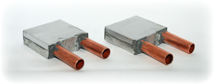
I then made the case out of a CD drive bay cover. The ones that came with my case were aluminium, and by chance were exactly the right width. The one I used was long enough to provide for both waterblocks.
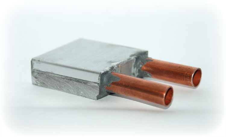
Next I had to leak test them all. I did this by blocking one end off, placing them underwater, and blowing into the other end. Any leaks would form bubbles. Only one leaked, which was one of the GPU blocks, and the fix was a simple blob of JB weld.
I didn’t build any more, as I’d bought not long ago a passive heatsink for the northbridge. It was from Zalman, and was actually terrible quality, but I left it for now. It was better than the tiny, high pitched fan that it had before. The power supply I kept as I didn’t want to remove ALL airflow – I deemed it pretty quiet already, and it should keep the air moving over the motherboard, passive northbridge sink, and RAM.
The Pump
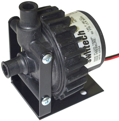
The first thing I bought was a caravan pump off ebay. This wasn’t suitable at all, it was noisy, it overheated when left on too long, and it was submersible, which meant I needed a separate reservoir. The next thing I got was from an aquarium shop, and this wasn’t any good either. It was too powerful, and it was far too big to even fit in the case. I have to say, I really tried to get a pump cheaply, but this is one area where buying cheap isn’t going to do any good. Eventually I shelled out the £60 for a Swiftech MPC655. It’s over-powerful, but this means I can turn the speed down, and the noise turns down with it. I do recommend buying a watercooling-designed pump, it’s leaps and bounds ahead of anything you can try and reuse.
I mounted it on elastic to keep the vibrations down too.
The radiator
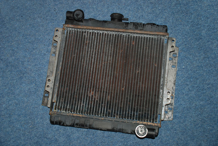
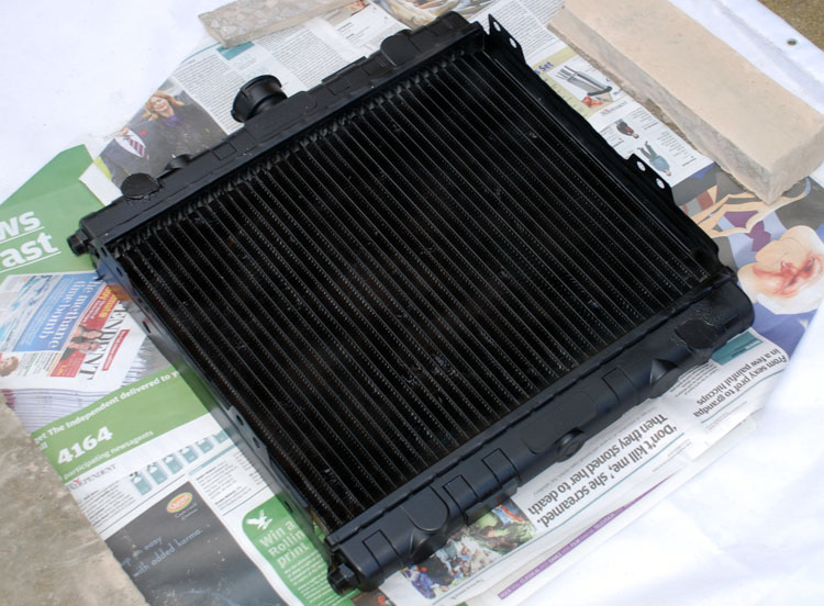
Trawling the scrap yards I finally found a suitable radiator, small for a car, but big for a PC. I was tempted to go for a very big intercooler, but it wasn’t quite big enough to cover the side of the PC. The radiator I got was the perfect size. I paid £15 for it. After cleaning it up and removing old pipes and things, it looked like this:
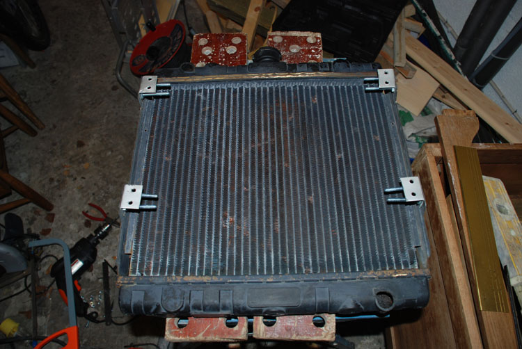
Above and below it are reservoirs. In this case they also act as manifolds to the different fins, so there was no getting rid of them. There are pluses and negatives to reservoirs, the positive being more water is used, the equilibrium takes longer to reach. The negative being that the more water you use, the less momentum the water can build up. At each cycle through the system, the motion of the water is just dissipated into the reservoir (as heat). However, if the pump is running well, this shouldn’t be a problem. Next I needed to work out how to attach the thing to the side of the PC, and how to connect the pipes up. I sawed off the excess metal and built little brackets to attach it. This was easier said than done. At first I built the brackets out of a piece of hardened steel, which simply melted my drill bits. Lacking anything else, I had to use some of my scrap aluminium.
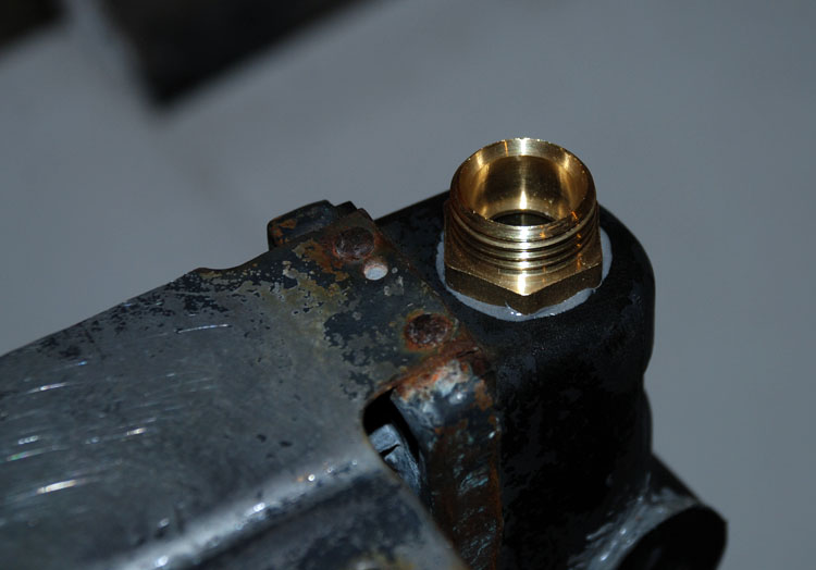
I removed the original fill ports since they were huge and in the wrong places. I cold welded plates over them, and fitted new brass threaded connectors.
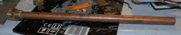
Diagonal flow through the radiator is needed, and since my new fill ports were going to be on the same side, I had to route the flow somehow. I fitted a nice length of scrap copper to the inside of the lower one.
As it turned out, almost all of the joints I made would leak before I even finished painting it. At several points I blocked off all the ports but one, and blew into it, and could hear the leaks. They were pretty easy to find, as it seemed that the joints had melted away against the plastic. At first I thought this was because the epoxy reacted with the plastic somehow, and tried another kind, but this also leaked. Eventually I decided that it was the oxides that had formed inside the radiator, that maybe they’d become acidic or something. I simply gave the areas a really good clean, and sanded them down a lot, to fresh, bare plastic, and tried again. As of yet, they’re all okay.
Cleaning the outside had been easy enough, just hosing it down and scraping. There weren’t nearly as many bugs and leaves as I’d expected. Cleaning the inside of all the old dirt and corrosion wouldn’t be so easy. The best thing I could do was to flush the radiator with boiling water. This involved filling it to the brim with scalding hot water, waiting, shaking, emptying, and repeating until the water came out clean. Since I had the two new filling ports at one side and the one old port at the top, which I had kept for filling when it’s attached to the case, I decided to block the old one and turn the whole thing sideways. Annoyingly, the first flush came out clean, which suggested I hadn’t waited long enough. The second flush I waited too long, and the bath plug I’d used to block the port expanded and popped out, filling the whole room with boiling hot water. Good fun.
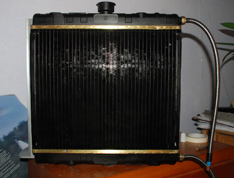
While sawing the sides off, I’d accidentally hit the bar connecting the plastic reservoir/manifold to the main copper body, and discovered it was brass. I took the opportunity to sand the whole thing down and expose the nice gold look. I masked the two parts I wanted to keep, then spray painted it all black.
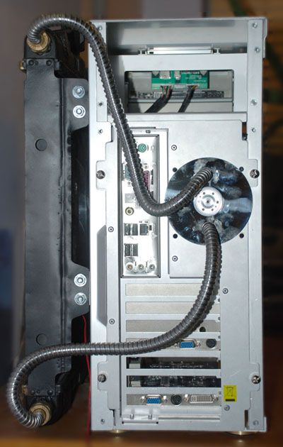
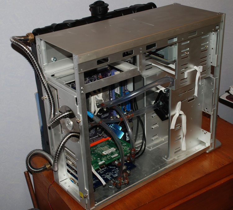
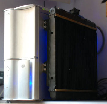
It took more paint than I expected because the surface area of those fins was so damn huge. It looked fine, but then from a different angle it seems not painted at all. The next thing I needed to think about was how to get the water to and from the radiator – in style. Another site that came up in my searches was the Orac3 project. Beautiful (and expensive) job, and also the inspiration I needed. As luck would have it, there was a spare chrome shower hose lying in a cupboard in my house. I sawed it in half (duct taping it, so as not to let the whole thing unwind, it’s happened before) and fitted it with brass nuts. Attaching the whole thing to the side of the case was a hassle, but far from impossible. And unlike the other car radiator projects I’d seen, it actually looks quite good.
The bolts I used, again just found in a tool box, were excellent in that they didn’t protrude into the case at all. There were only eight of them though, the other parts of the brackets I had to use sawn down off cuts. I also nearly had not enough bolts, and had to search everywhere for spares.
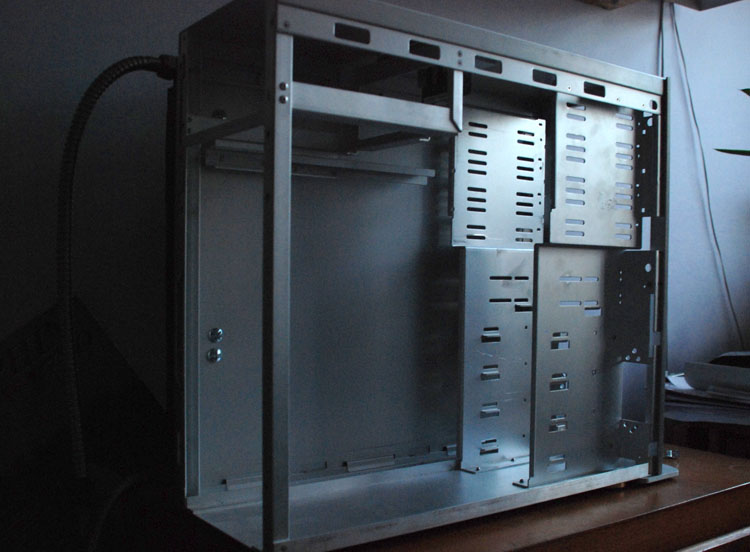
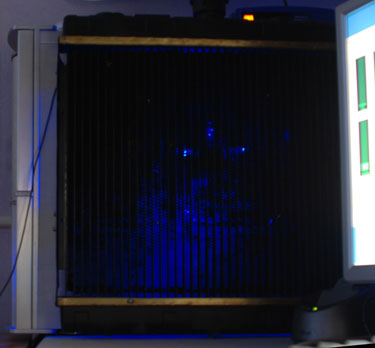
As I talked about earlier, these radiators are designed for forced convection – that’s why the fins are horizontal, and so close together. I fitted a 20cm case fan to the inside of it, with the intention of running it very slowly, just so that there is slight airflow overall.
The only place in the motherboard tray I could fit the pipes through though was where I’d removed one of the case fans.
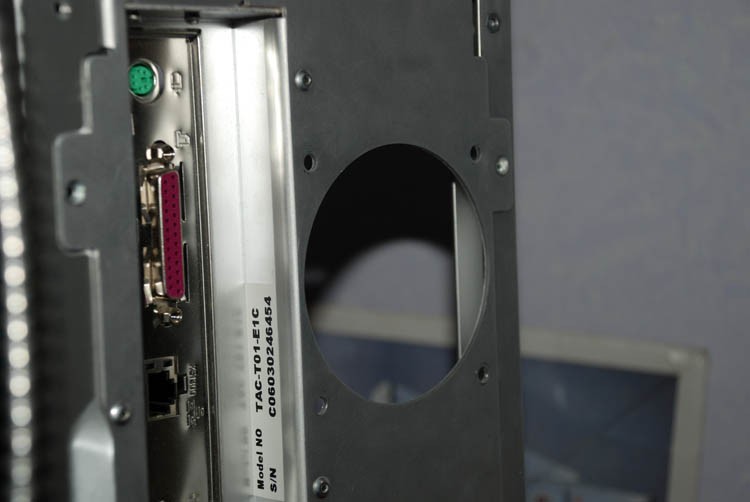
This hole was far too big and needed to be blocked off anyway. In my search for suitable bits of scrap I found an old hard drive. The memories! This thing was what got me banned from stealing old computer parts from my nearest old-computer-parts-dumping-ground. Data protection act, and shizzle.
I hate the faraday-cage casing of hard drives, they’re really annoying to disassemble. I got frustrated with it and drilled through all the screws.
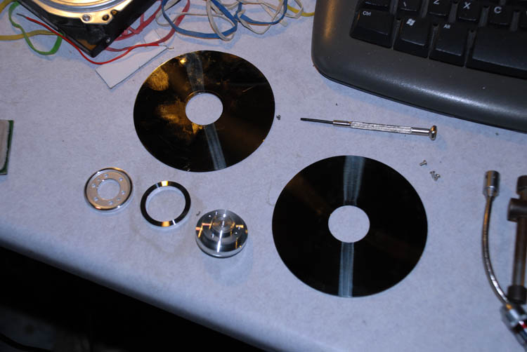
The platter came apart quite easily, despite the torx screws. One of them had been damaged by my angry destruction of the case, so I placed this one on the inside. I used the two plates as a clamp around the hole it was filling, as they were slightly wider diameter than the hole. After checking this would work, I masked one of them off and drilled holes for the pipes.
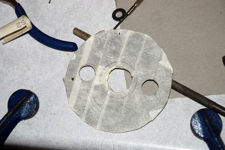
They fitted perfectly. Horay.
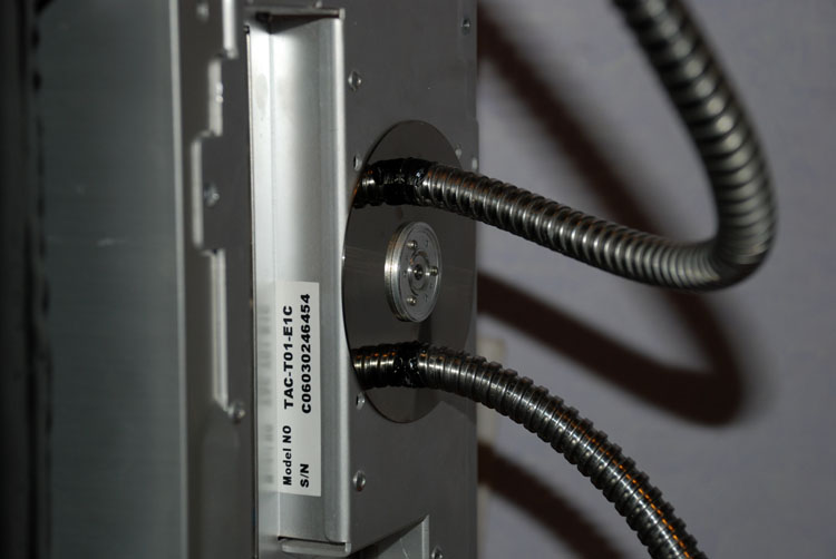
Of course in the flash of the camera, even the faintest fingerprints get shown up on the mirror finish of the platters. You’ll have to take my word about how sweet it looks.
Assembly
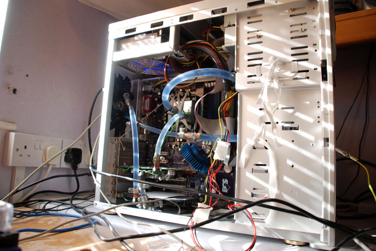
Remember kids, always earth yourself when trying this at home! Static can ruin circuitry, and the motherboard was in open air for so long it was quite likely to get fried. Of course I couldn’t tell if it had been until I’d finished the project.
Building mounts for the waterblocks was hard. If I’d planned ahead properly, I would have added places to attach them on the actual blocks. But as I didn’t, I had to make do with what I could. GPU heatsinks usually attach by plastic, spring loaded clips called nipples (lol). I bent some scrap bits of metal into roughly the right shape, and drilled some holes in the right place for the nipples to go. This worked decent enough.
The CPU one was even trickier. At first I tried this screw-design:
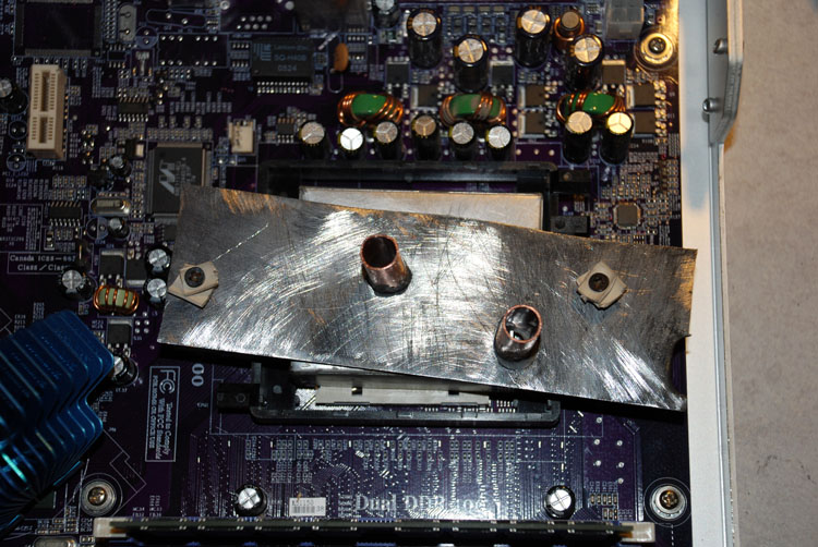
But that was so awkward to set up that I scrapped it, too. In the end I actually used plain old elastic. The CPU had the plastic mountings from the original heatsink still attached to the motherboard, and I used it as a frame to hook elastic around and tie the waterblock in place. It worked better than I was hoping, although it was still difficult to set up.
For all the thermally conductive parts, I used Arctic Silver 5, a tube of which I got from ebay for £3.
I needed to plan the pipe work. Things to consider are the distance of pipes used, the ease of the joints (sharper means less flow), and whether to place parts in series or parallel. My original idea was to place the CPU first, then the GPUs in parallel. After thinking it through though, this would mean adding Y junctions, and after all the main graphics card will be making more heat than the secondary.
The recommended route in most setups is:
Resevoir > Pump > Radiator > Waterblocks > Reservoir
However, because the radiator and reservoirs were connected, this would mean the flow would mostly dissipate in the radiator, meaning it would be pointless to place it first. I settled on this:
Radiator > Pump > CPU > GPU1 > GPU2 > Radiator.
The only problem with this is the drawing power of the pump needed. Because the radiator is a distance away, it takes a lot of effort to suck the water to the pump. I couldn’t see any easy way to avoid this though, other than placing the pump physically below the radiator, which was out of the question.
As I started piping things together, it became obvious that I’d made a mistake with the GPU blocks. While I’d placed the cards as far apart as possible, the bend was still too sharp, and the pipe either stuck so far out the case wouldn’t close, or kinked, blocking the flow.
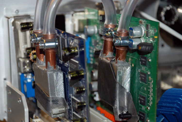
I would have to use elbow joints. It’s best to steer clear of these normally, as they restrict flow, but here I’d have no choice. At first I tried building them out of just piping and my other epoxy, Petro-patch putty. This was like play-dough that set like rock and smelled like a dead pig.
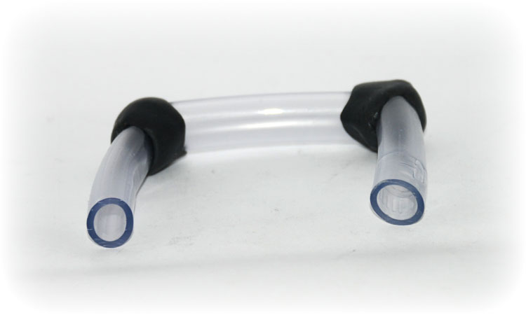
It was a miserable failure, the acrylic pipe was just too flexible. I built a similar thing then using copper pipe, which was fine, but this meant it needed more transitions from copper to acrylic – each requiring another jubilee clip.
As I was running out of clips, I improvised the join for the shower hose to the acrylic pipe. I connected them with copper pipe (which took a lot of heating them in boiling water and shoving) and then coated it with the leak patching putty. It then needed filing down so that it could fit through the holes in the hard drive platter.
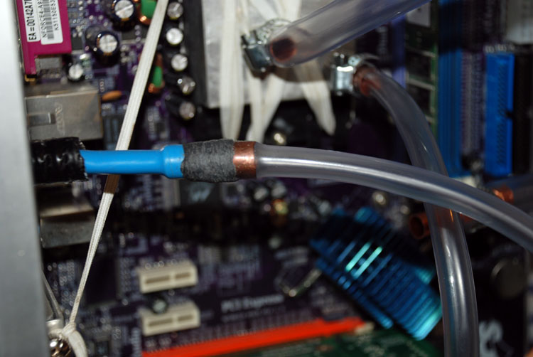
Just in case it doesn’t work, at this point I declared it a work of art.
There are a few corrosion ideas we need to consider next. Oxidation will occur when there’s air in the fluid – and there shouldn’t be much of that. But also there’s this annoying thing called galvanic corrosion. Essentially we’re using different metals in an electrolyte (the water) and over time the more reactive of the metals will fall apart. There’s a nice page about it here. I’ve mixed aluminium, copper and brass in the build, so to prevent galvanic corrosion I needed to add a sacrificial lamb – a block of zinc. Harder to come by than you might think at first, but eventually I realised I needed so little, I could use a galvanised nail. They’re hot-dip coated in zinc (usually), and should last at least six months.
On top of that I’ll be using distilled (de-ionised) water. This is supposed to be non-conductive, but you can’t count on that, as my homemade continuity tester gave a beep. Mind you, it picks up very, very tiny currents, so it’s probably non-conductive for all practical purposes. I don’t plan on it leaking when the PC is turned on, anyway. Also in the mixture is antifreeze, since it usually helps prevent corrosion.
Testing
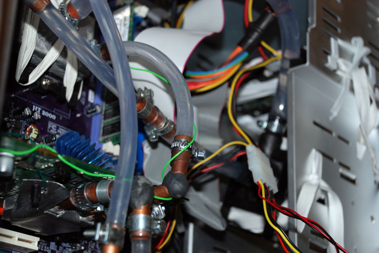
I poured in the fluid, and turned the pump (and only the pump) on. It’s a molex connector, but you can activate the power supply by connecting the green wire to ground. At first there were plenty of bubbles zooming round, but they cleared in minutes. Also within minutes, a leak appeared on the CPU. I tightened the jubilee clips and tried again. Still leaking.
I took the whole thing apart and leak tested the CPU block – nothing. And yet, it was still leaking when I connected it up again. Only a few drops a minute, but still completely unacceptable. I dried the whole thing and tried to find where the leak was coming from, to no avail.
I must have dismantled and patched the CPU at least 20 times. By the end, the amount of patches on it was completely ridiculous. It had grown to almost twice the size, just covered in epoxies. In the end, though, it finally stopped leaking.
Strangely, neither of the GPU blocks leaked. The radiator leaked, and I had to take it apart, unbolt it from the frame, sand down the area and patch again, but then it was fine. I had to drain and refill the fluid so many times that I built a little funnel to help me with it.
When it eventually ran for 24 hours, non stop, without leaking, I decided to turn it on. I completely replaced the fluid as the old stuff had collected a lot of dirt from the containers it had been in. And when I turned it on – wonder of all wonders – it didn’t explode!
Yes, a miracle. At first I just kept the bios PC health screen open to see if the temperatures were anywhere near okay. They were, thank god. Then, booting up – there were a few driver issues, as I’d used the hard drive in another computer since – which caused several disconcerting blue screens of death. At first I was convinced I’d ruined some of the hardware, but after some tinkering, it was all good.
I used speedfan to watch the temperatures as I turned on CPUBurn. I’m unsure about whether the equilibrium point is really reached this quickly, but from my initial tests, the CPU’s equilibrium point is at around 33C idle, and up to 42C under full load. It reached it in a matter of minutes, and hadn't budged in half an hour. Which is pretty impressive. More amazingly, I turned the pump down gradually, testing each time, from the highest speed down to the slowest, and the temperatures remained identical. I switched the main fan down to 5 volts, and still, the temperatures were rock solid, never above 42C.
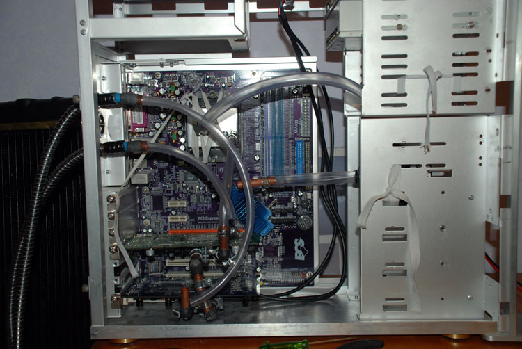
Next I reassembled the rest of the computer. I lined most of the inside with old carpet, to absorb as much sound as possible. I also placed a speed control switch on the front for the fans, and a place you can insert a screwdriver to adjust the pump speed without dismantling anything.
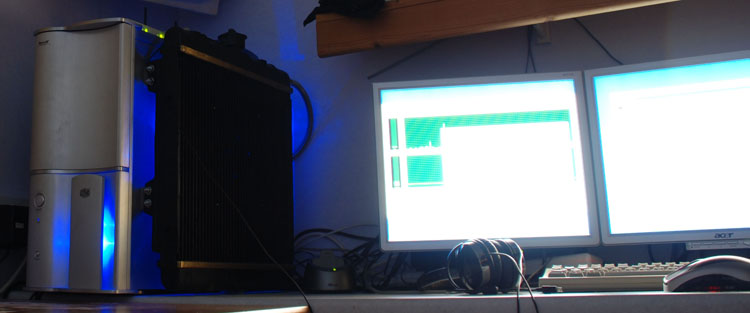
The blue LEDs on the radiator fan look quite nice actually. They appear different from different angles, it’s hard to capture in a single frame.
I’ve got more testing to do, obviously, and I’ll not know the limits of this cooling system until I’ve overclocked it to the max, but for now I’m enjoying the phenomenal cooling power I’ve got. It’s been two weeks and no leaks yet.

And is it silent? Compared to before, yes. The loudest part is now the PSU fan, which was the quietest part before. Annoyingly, it developed a slight rattle after putting everything together again, but it disappears after a few moments. I guess if I were to change anything now, if I had the effort, it would be to watercool the northbridge and PSU.
Naturally, it’s taken me so long to build this thing that most of it’s out of date. Still, I’ve never met anyone with a more awesome rig. I’ll upgrade most of the parts soon, and then I’ll start overclocking it to see just how powerful this radiator is.
Evaluation
TemperaturesI downloaded a new version of speedfan and this time it could pick up the graphics cards' temperatures. They weren't quite so pretty as the CPU. Generally their equilibrium points were around 52C, which isn't bad, but isn't brilliant either. I'm not sure why this is, it may be because they're placed after the main CPU block, but more probably it's that the design of them isn't as great.
After some searching, I found this waterblock which looks brilliant, and strangely is almost exactly the same design as mine. Mine maybe isn't quite so tidy, but still. The design of the GPU blocks isn't as great as it could be - if there had been more fins inside each one they may have performed better.
Another interesting thing is that Zalman have brought out another Reserator, which looks much more like my side-mounted design.
Cost
The main parts were:
Radiator: £15
Pump: £60
Acrylic Tubing: £2.50
Artic Silver: £3
JB Weld: £5.95
Antifreeze and de-ionised water: approx £7
Elastic: 85p
I use JB Weld for all kinds of things, so it's not really a cost of the project. And I bought much more antifreeze and de-ionised water than I needed, but I guess that can help me out the next few times I change the fluid. There was also the money I wasted on things I didn't use, like the other pumps, although I got most of my money back. I think it's fair to budget this build at £100, which isn't bad at all for a fast, silent, watercooled-to-the-max PC. You can pay hundreds for watercooling kits that are louder and not as effective as this.
And not nearly as fun to build.

Update
One year on, and against all odds, the machine is still alive. More than alive - it's still silent, and it's still super quick.I've amazed myself with how well this turned out. There have been no leaks, nothing's exploded, the CPU is barely ever above body temperature. I currently have the CPU clocked to 125% of its stock rating without any increase in monitored temperatures.
The only sad thing is that the hardware is now old and outdated. While I could replace the main parts and reuse the radiator, pump and waterblocks, I think I'll probably leave the machine in one piece as a tribute to how much effort and time I threw at the project when I should have been revising for my A-levels.
The next rig I make will probably be even better.