
| DAVID | Posted: 17 Nov 2018, 11:29 PM |
|---|---|
 I love mcus Member Posts: 237 Joined: 10-September 17 |
hi, after watching your post an video about the topic (and also about your synth cables) i could not resist to try it out, so i grab my attiny85, load the code and fuses, and so i am ready to go, i had a lot of fun with it but the thing missing was polyphony and wanted to stay with the tiny85 instead of changing to the attiny2313 or atmega328 and finally i get it working. it uses resistors to sum the squarewave output of 3 pins like in your polyphonic version to generate the audio signal, it can run at 8 or 16mhz but sadly since i am terrible at using timers i ran out of them so i can not use pwm. if you want to check it out i leave the code on github and an audio. code:https://github.com/theawsomeavr/attiny85-synth tetris theme:http://s000.tinyupload.com/index.php?file_id=09320284949565457196 update: i also got it to work with v-usb so it is an improvement to the 2 voice polyphonic even sillier usb midi synth Last edit by DAVID at 19 Nov 2018, 08:21 PM ------------- |
| [top] | |
| DAVID | Posted: 19 Nov 2018, 04:47 AM |
|
I love mcus Member Posts: 237 Joined: 10-September 17 |
here is my video about the topic:https://www.youtube.com/watch?v=cTDyIzufIW0 ------------- |
| [top] | |
| mit | Posted: 19 Nov 2018, 03:21 PM |
 yeah whatever Admin Posts: 687 Joined: 4-May 16 |
Nice. I wonder how loud it is? I always found mine to be quieter than I'd like. In the USB smallest synth I had the piezo driven differentially (so it's between two GPIO pins, and when one goes high, the other goes low, so it effectively gets twice the voltage) but with summing multiple pins I don't think that could work. Then again, the speaker you're using is quite different to a piezo and probably doesn't need as much voltage. ------------- |
| [top] | |
| DAVID | Posted: 19 Nov 2018, 06:35 PM |
|
I love mcus Member Posts: 237 Joined: 10-September 17 |
well i cheat i little bit and use a transistor to drive the speaker that explains the loudness schematic: USB:https://easyeda.com/elpro/usb_midi_synth_MKII MIDI:https://easyeda.com/elpro/attiny85_midi_synth Last edit by DAVID at 19 Nov 2018, 08:54 PM ------------- |
| [top] | |
| DAVID | Posted: 27 Dec 2018, 02:45 AM |
|
I love mcus Member Posts: 237 Joined: 10-September 17 |
i got a question. How did you detect on your polyphonic to know which pin to toggle, because i finally got the attiny85 to work with the software serial and pwm (with phase and frequency correct pwm on timer0 and be 4 voice polyphonic) but then i decided to add a fifth voice and then i ran in to performance issues, it is running at 16 mhz and it very often does not detect note off commands. so the way i detect to which channel oscillator (for then writing it to the pwm output) is with a bunch of if conditions. i call "void loop" various time like a break; for skipping all the other "if" conditions and so then make it more "efficient" i put the full code on:https://github.com/theawsomeavr/attiny85-synth/tree/master/attiny_synth_5_voices_experimental schematic:https://easyeda.com/elpro/attiny85_midi_synth pre compiled hex files on:https://github.com/theawsomeavr/attiny85-synth/tree/master/hex%20files fuses: ext:0xff high:0xdd low:f1 byte prevnote; would it be because this is in c and not assembler? ------------- |
| [top] | |
| mit | Posted: 31 Dec 2018, 01:35 PM |
|
yeah whatever Admin Posts: 687 Joined: 4-May 16 |
Being in C and not assembler is part of it, but you should still be able to do almost as good in C, if you optimize it a bit. I think the problem is probably with the part that is getting the midi notes. The attiny85 doesn't have a hardware USB port, or even a hardware UART port, so whichever one you use it will be implemented in software. Doing that (I assume you're using the arduino library for it) will take up most of the processor time, leaving not much left for everything else. If you implement your own software UART it might be possible to speed it up a bit, but probably not by much. ------------- |
| [top] | |
| DAVID | Posted: 1 Jan 2019, 12:03 AM |
|
I love mcus Member Posts: 237 Joined: 10-September 17 |
i had no luck getting it to work. i tried to use the _delay_loop_2(); function and i did not get any successful results. it only works when the TIMER0_COMPA_vect is remove from the code. void setup() {this is the way i read the Serial data ------------- |
| [top] | |
| DAVID | Posted: 1 Jan 2019, 12:24 AM |
|
I love mcus Member Posts: 237 Joined: 10-September 17 |
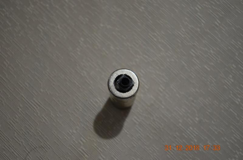
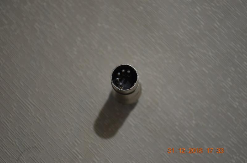
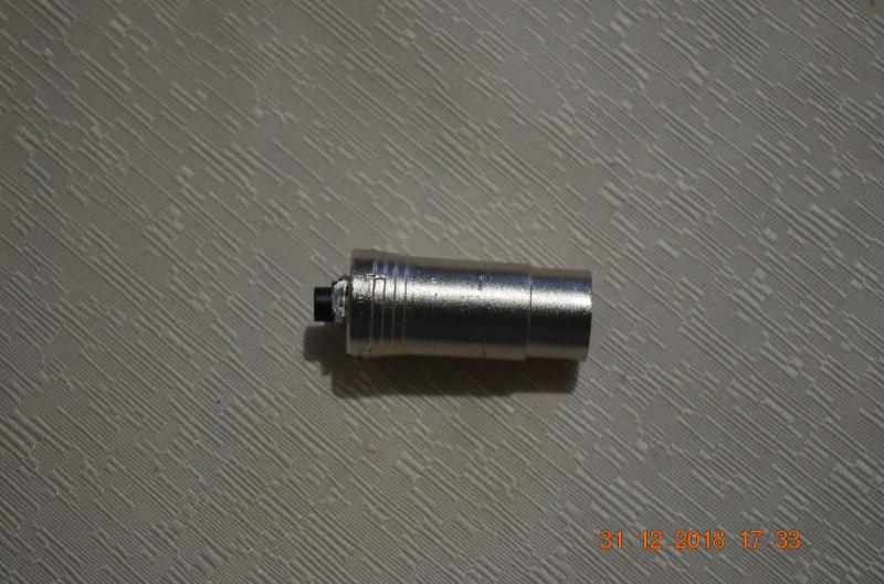
i got tired and desired to just use 4 voices and build it inside a midi plug with an audio jack at the other side 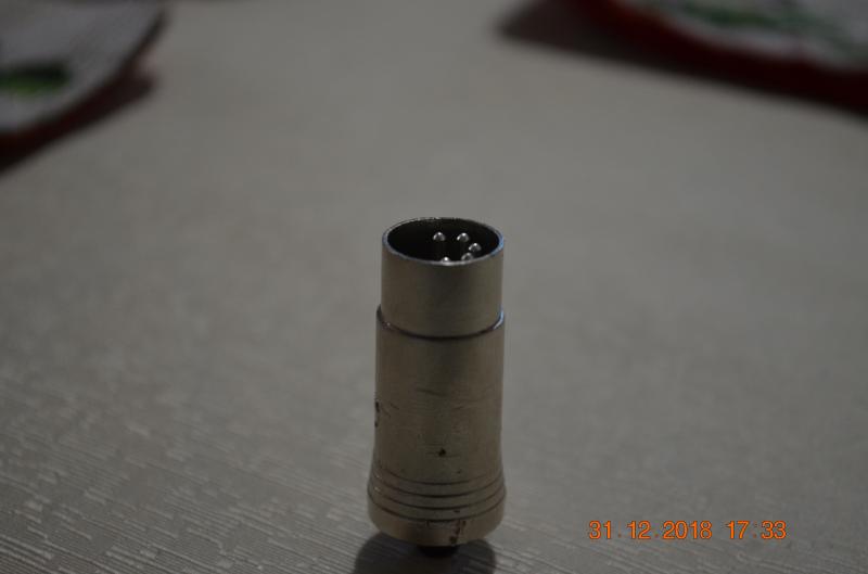 Last edit by DAVID at 1 Jan 2019, 12:36 AM ------------- |
| [top] | |
| DAVID | Posted: 1 Jan 2019, 12:30 AM |
|
I love mcus Member Posts: 237 Joined: 10-September 17 |
   ------------- |
| [top] | |
| mit | Posted: 1 Jan 2019, 01:32 PM |
|
yeah whatever Admin Posts: 687 Joined: 4-May 16 |
Very neat. QUOTE
i tried to use the _delay_loop_2(); function and i did not get any successful results. That probably means the delay routine is using the timer. You could make your own delay routine, but it might not work well if there are other interrupts. You could make the logic of your shifting more efficient by shifting each bit as it comes in, instead of using an array. Something like
Might need to shorten the delay a bit. ------------- |
| [top] | |
| DAVID | Posted: 1 Jan 2019, 11:35 PM |
|
I love mcus Member Posts: 237 Joined: 10-September 17 |
so now it works fine. the _delay_loop_2(); function execute 4 clock cycles of the CPU and so it did not work since it was getting interrupted by timer0 compa vect. So the only thing that i have to do was to set to 0 the TIMSK register when i detect the PB4 is at 0v and then enable it when we have the whole midi byte. also my code reduce the use of memory to half of the original (from 4kb to only 2kb) byte serial_read() {Last edit by DAVID at 1 Jan 2019, 11:36 PM ------------- |
| [top] | |
| E3V3A | Posted: 10 Jan 2019, 03:21 PM |
 Member Posts: 3 Joined: 10-January 19 |
This seem like a great project for kids and adults alike. But since I have not built it yet, I am curious to know about it's limitations. I.e. How many voices does it do? (Last post mentioned 4 but there is 5 in the repo...) Does it handle pitch-bend and other things when using a USB/Midi keyboard and its dials? What are the additional hardware/software required to program the ATTINY85? Is there any schematics for using the USB input and phono (headphone) output? (I only found for using tiny speakers.) Cheers! E:V:A ------------- |
| [top] | |
| DAVID | Posted: 10 Jan 2019, 10:15 PM |
|
I love mcus Member Posts: 237 Joined: 10-September 17 |
hi, for programming the attiny85 you can use an arduino, usbasp, usbtinyisp, etc.... it does not handle pitch bend, and it is stable at 4 voice (only if you don´t play random keys all at once). in general i would recommend trying out my midi synth based arround the arduino rather than the attiny85. and if you are planing to use usb you can use the smt32 board instead ------------- |
| [top] | |
Sign in to post a reply.