
| Shran29 | Posted: 5 Jul 2024, 10:11 PM |
|---|---|
 Member Posts: 11 Joined: 5-July 24 |
Heya, I just finished making two of these precision clocks (one for PST and one for JST). The PST Clock performed flawlessly upon start up. The JST Clock however, it is displaying accurate time for Japan (near as I can tell from my current location on the American West Coast) but the date and time down to the seconds indicators and the timezone LED's are flashing every second. When the digits are flashing they alternate between the digits for the correct date and time and displaying hyphens. Anyone who has experienced this or has suggestions would be greatly appreciated! ------------- |
| [top] | |
| mit | Posted: 6 Jul 2024, 09:34 AM |
 yeah whatever Admin Posts: 687 Joined: 4-May 16 |
That sounds as if the chip is resetting each second. My first inclination would be to check if there is some kind of short, or capacitive coupling (flux residue etc) between the PPS signal and the ATtiny's reset pin. Does this happen immediately after turning on, or is it only once the module gets a fix (led blinking)? What power supply are you using, if you swap power supplies between the clocks does the problem remain? I started shipping clocks with a different GPS module recently so I'm still on the lookout for any new problems that might arise. All of the modules are tested here before they get sent out though. ------------- |
| [top] | |
| Shran29 | Posted: 6 Jul 2024, 08:49 PM |
|
Member Posts: 11 Joined: 5-July 24 |
This clock had the smaller module yes. I tried a different power supply today (one that allows me to monitor V and W in real time) and it performed perfectly for the first few minute (maybe 10min max?) before it started doing the hyphen/digit alternating again. It is currently running on ~5.15V from the power supply. ------------- |
| [top] | |
| Shran29 | Posted: 7 Jul 2024, 02:21 AM |
|
Member Posts: 11 Joined: 5-July 24 |
Update: On further observation the oscillation appears to be occurring every half second, not every second ------------- |
| [top] | |
| Shran29 | Posted: 7 Jul 2024, 05:19 AM |
|
Member Posts: 11 Joined: 5-July 24 |
Also, just did a more thorough observation of the clock after starting it up post a 45 minute period of being turned off. Just prior to the oscillation of the digits I noticed the seconds digits begin to run through must quicker than individual seconds ------------- |
| [top] | |
| mit | Posted: 7 Jul 2024, 09:56 AM |
|
yeah whatever Admin Posts: 687 Joined: 4-May 16 |
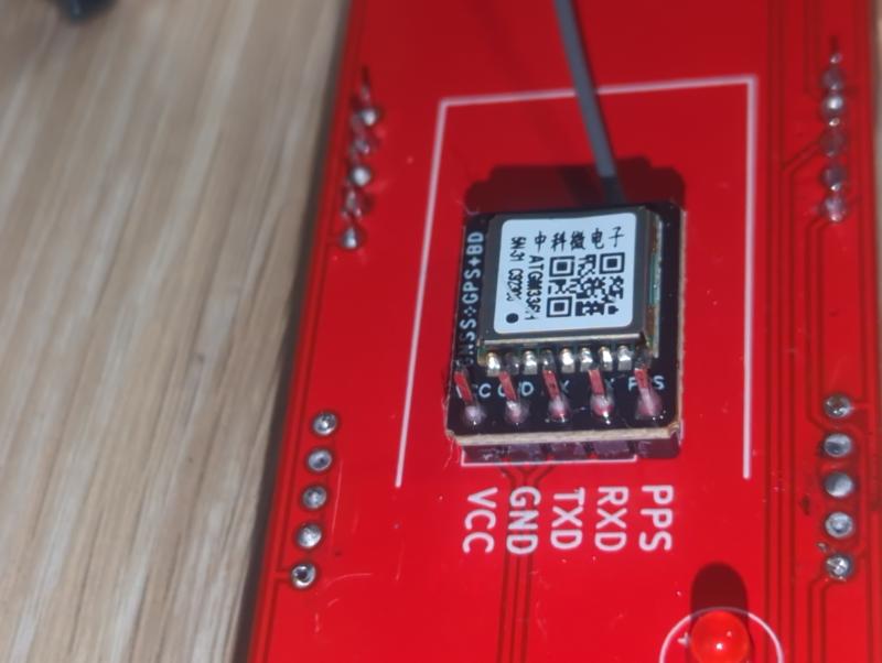
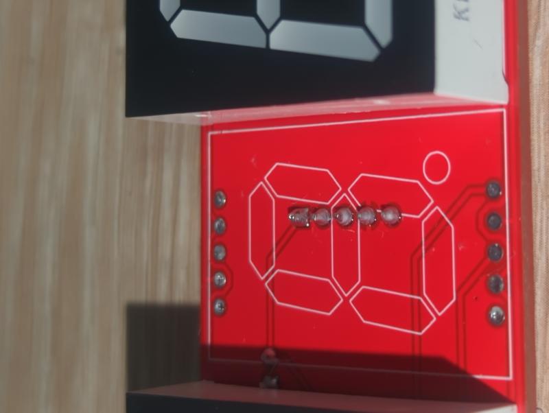
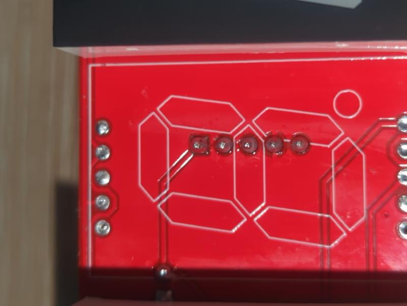
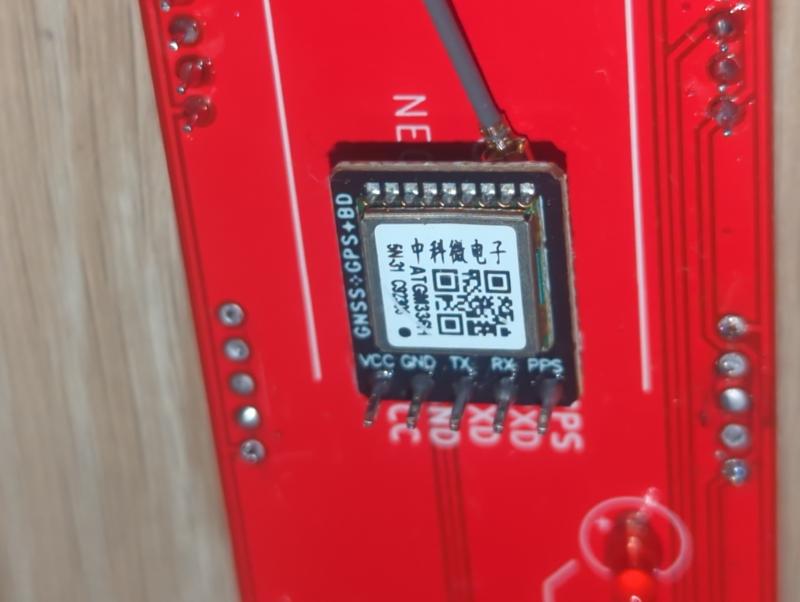
It sounds like there is a soldering mistake on the PPS signal. PPS only starts pulsing once it gets a full GPS fix, which explains why it works for a bit before this happens. If not the reset pin, it could be a short between PPS and ground. How do the LEDs look on the back of the clock? The "PPS fix" LED is directly tied to PPS, it should be off until it gets a fix, then blink briefly once per second. The LED on the module itself should be on continuously, but turn off briefly with each PPS pulse. If you can check continuity between PPS and ground, and between PPS and other pins, it might shed some light. There's the interactive board viewer here. If you're able to take a picture of the soldering on the pins for the module, ideally looking between the digit and the board behind the GPS module, it might help me spot something. ------------- |
| [top] | |
| Shran29 | Posted: 7 Jul 2024, 06:45 PM |
|
Member Posts: 11 Joined: 5-July 24 |
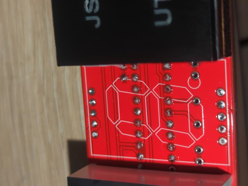
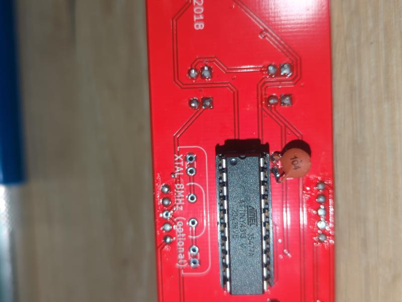
On the GPS module pins: 1) PPS to GND; 278.4kΩ 2) PPS to VCC; 0.83MΩ 3) PPS to TXD; 1.37MΩ 4) PPS to RXD; 500MΩ The PPS light on the GPS module is continuously on except for the split second when the GPS LED blinks on. I will attempt to desolder one of the front display modules to have full view/access to the solder joints underneath where the pins for the GPS module are and get a picture/see if I can spot a bad solder job that I may have missed. ------------- |
| [top] | |
| Shran29 | Posted: 7 Jul 2024, 09:17 PM |
|
Member Posts: 11 Joined: 5-July 24 |
     ------------- |
| [top] | |
| Shran29 | Posted: 8 Jul 2024, 12:17 AM |
|
Member Posts: 11 Joined: 5-July 24 |
     ------------- |
| [top] | |
| Shran29 | Posted: 8 Jul 2024, 03:34 AM |
|
Member Posts: 11 Joined: 5-July 24 |
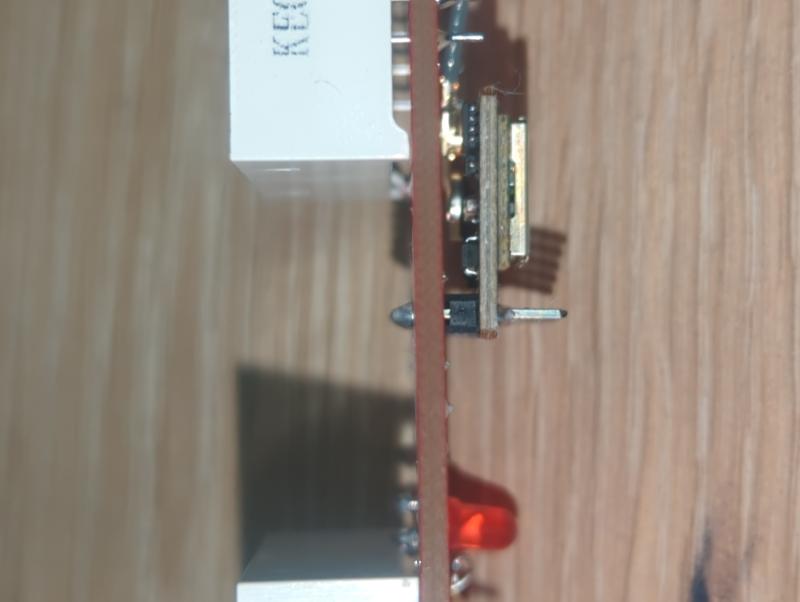
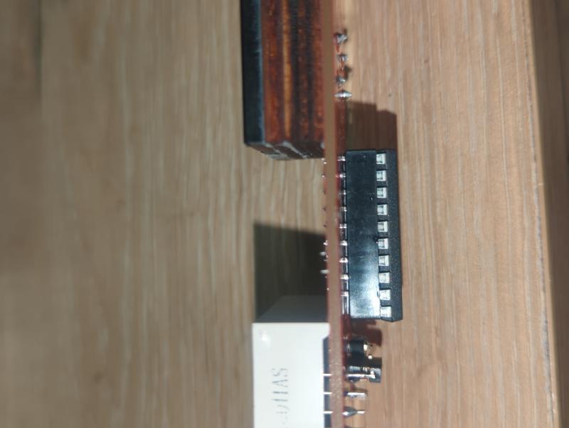
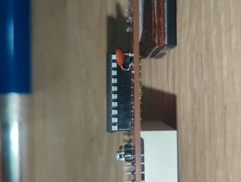
Noticed the socket on the Tiny is missing a pin, could this be the cause of the troubles or is it supposed to be unused? ------------- |
| [top] | |
| mit | Posted: 8 Jul 2024, 08:58 AM |
|
yeah whatever Admin Posts: 687 Joined: 4-May 16 |
Aha, that will be it. Beautiful soldering there, sorry for doubting you. Looks like the ground pin is missing. The chip only functioned because it was probably using the PPS signal as a return current path, and when it went high the chip reset. The quickest way to repair it would be to find another socket (or I can post one to you) and pull the pin out from it. They slide out of the plastic with some encouragement. Alternately, replace the whole socket if you're up for it, or maybe try and remove and swap one of the other pins on that socket that isn't used, some of the pins of the ATtiny are not connected to anything. To bodge a quick repair/test, you could solder a wire to a nearby ground pin (anything connected to the copper pour) and poke it into the socket to make contact with the chip's leg. ------------- |
| [top] | |
| Shran29 | Posted: 8 Jul 2024, 07:25 PM |
|
Member Posts: 11 Joined: 5-July 24 |
Haha Thanks for the compliment but I can tell I'm a bit out of practice. There some excess solder and some overheating on some of the joints I did and I should have gone back over the clipped ends of all the leads with the thinnest coat of solder possible. My old instructors would definitely have failed me on these, despite the fact that they will still function just fine. Glad we figured out what the issue is! I'll probably just make a trip to a hobby/electronics store and pick up a new socket to either steal a pin from or replace the whole socket. Just to make sure I get the right one, could you send me the specs and/or recommended manufacturers? ------------- |
| [top] | |
| Shran29 | Posted: 9 Jul 2024, 12:03 AM |
|
Member Posts: 11 Joined: 5-July 24 |
On an unrelated note, but as long as we're here discussing, I was reading through the information packet when trying to troubleshoot on my own and took note of the optional installs. I plan to install the upgrade antennae you recommend there, but was curious why you only recommend an 8MHz crystal vice something like a 16MHz? ------------- |
| [top] | |
| mit | Posted: 9 Jul 2024, 07:49 AM |
|
yeah whatever Admin Posts: 687 Joined: 4-May 16 |
QUOTE (Shran29)
I'll probably just make a trip to a hobby/electronics store and pick up a new socket to either steal a pin from or replace the whole socket. Just to make sure I get the right one, could you send me the specs and/or recommended manufacturers? It is simply the cheapest style of DIP / DIL socket. The more expensive style has machined pins. Both types will cost less than the postage if you order them online. (Perhaps I should start shipping kits with sockets with machined pins, maybe that would have avoided this problem.) QUOTE (Shran29)
was curious why you only recommend an 8MHz crystal vice something like a 16MHz? Not sure what the perceived benefit of 16MHz would be. It's 8MHz only because the internal oscillator on the chip is 8MHz, and so the code is written to run at 8MHz. Both 8 and 16 MHz crystals would be AT-cut, and there are differences between those and the tuning fork 32.768kHz you'd find in a normal watch or clock. The AT-cut crystals will use more power but be less sensitive to temperature. ------------- |
| [top] | |
| Shran29 | Posted: 9 Jul 2024, 06:38 PM |
|
Member Posts: 11 Joined: 5-July 24 |
Sounds good to me! I just check. I only asked because my background is in operations, maintenance, and repairs in compliance with standardized procedures. So why and how certain components are selected is not something I know much about, but am always trying to learn more of. When looking and doing a bit of research at the optional components listed I found that Adafruit had a few different options but did not have any 8MHz. But yeah, just asking questions and trying to learn different things. ------------- |
| [top] | |
Sign in to post a reply.