
« PreviousPages: 1 [2]
| QxStuart | Posted: 16 Jan 2020, 11:35 PM |
|---|---|
 Member Posts: 10 Joined: 13-January 20 |
This afternoon I did a cold start in a poor indoor location; on a brick fireplace mantel. Time to acquire time & date = 0:40 Time to sync and produce PPS = 1:40 Here are some photos of the Pulse/Larsen active antenna. I selected the smaller 15dB gain after reading the ublox receiver might have trouble with a 30dB gain antenna. But specs for current version of ublox may be ok with 30db antenna (same cost but larger). 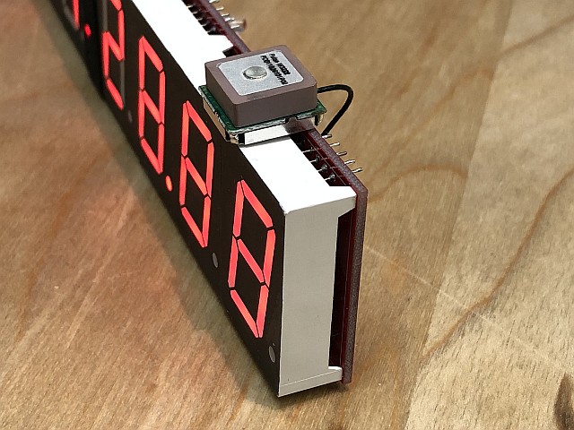 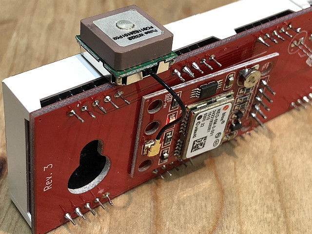 If you update instructions, mention to verify 5-pin header for GPS Rx is perpendicular before soldering. ;) Also describe meaning and relationship between GPS LED, "GPS FIX" LED, and colon LEDs. And exactly how did you configure the ublox for this clock application. John Bay Area, CA, USA Last edit by QxStuart at 16 Jan 2020, 11:36 PM -------------QXStuart San Francisco Bay Area |
| [top] | |
| mit | Posted: 17 Jan 2020, 08:25 PM |
 yeah whatever Admin Posts: 687 Joined: 4-May 16 |
QUOTE
OK, will do.If you update instructions, mention to verify 5-pin header for GPS Rx is perpendicular before soldering. ;) I can tell you now the LED descriptions: - the "GPS fix" LED is wired directly to PPS. If the module is outputting PPS, it has at least a 2D fix. Unlike anything controlled through software, this LED should light up with extremely good timing accuracy, the signal is supposedly accurate to within 50 nanoseconds. - the LED on the module is essentially the same thing as "GPS fix" but wired up inversely. - the colon LEDs are toggled when the microcontroller receives the PPS signal. Specifically, it toggles the colon LEDs whenever it trims its oscillator to track the PPS signal. The centiseconds are interpolated and the software tracks the PPS interval in a similar fashion to a phase-locked loop. There is actually debug data shown in the timings of the update, this was mostly for my development purposes but it can be seen without the aid of a 1000fps camera. Depending on whether the internal oscillator is fast or slow, there is a 100 millisecond delay to the colon toggle. When the interpolation has settled, it should alternate between fast and slow every few seconds. QUOTE
The configuration for the modules can be quite complex, but because I was worried about the fact the config is stored in the battery-backed ram, I made sure to use the module with its default config. The standard output contains the $GPRMC message, which has all of the info we need, along with the PPS to get the timing exactly right.And exactly how did you configure the ublox for this clock application. ------------- |
| [top] | |
| QxStuart | Posted: 18 Jan 2020, 01:32 AM |
|
Member Posts: 10 Joined: 13-January 20 |
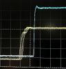
I can verify your “accurate to within 50 nanoseconds” based on the following tests I just ran. In the following oscilloscope screen photos: • Yellow trace (Ch.1) is the 3V PPS from the Mitxelta Precision Clock “GPS Fix” LED circuit. • Blue trace (Ch.2) is a 5V PPS from a Jackson Labs Fury GPS disciplined 10 MHz oscillator. • Scope is triggered by 5V PPS from a HP 58503A GPS disciplined 10 MHz oscillator. 1st photo shows 100 ms long PPS from Mitxelta, and 200 ms long PPS from Fury. 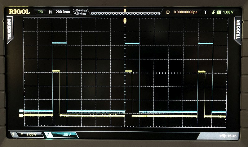 2st photo shows persistence traces from four PPS signals. The Mitxelta has about 20 ns of expected jitter. The Fury and HP trigger (at center “T”) has very little relative jitter because they are both derived from very stable 10 MHz oscillators. 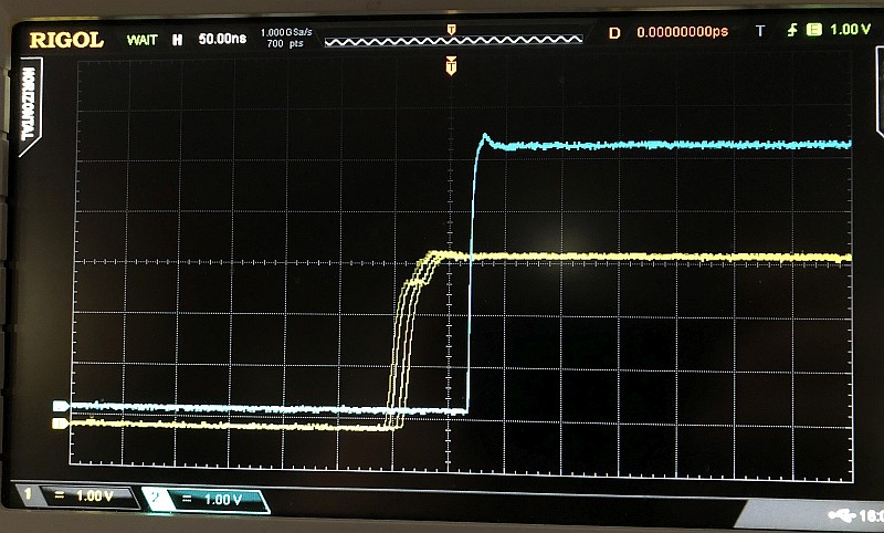 3rd photo expands the horizontal scale to 10 ns/div, and shows Mitxelta jitter over about 80 ns. I think this was due to weak GPS signals at the time, maybe only 2 or 3 satellite solutions. 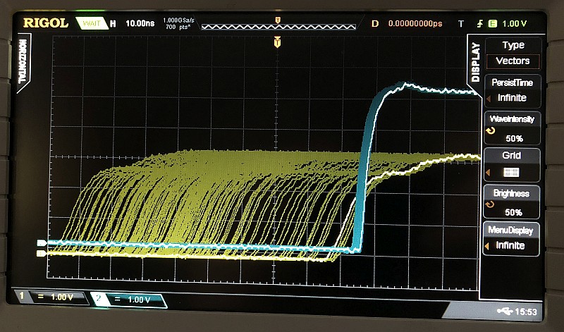 4th photo with the scale back to 50 ns/div, is more typical of the Mitxelta over the past 30 minutes. 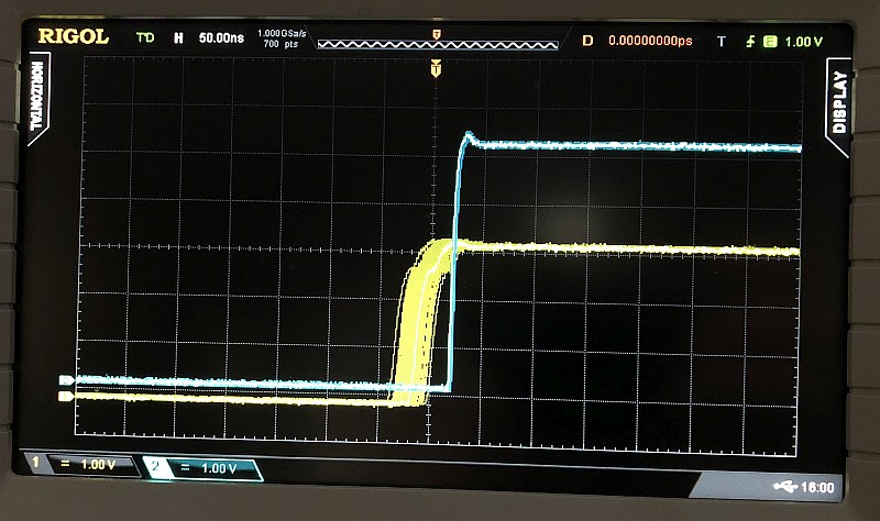 Note, the relative timing offset between the three PPS sources is due to antenna cable length and receiver processing latency. The Fury and HP GPS receivers have manually set delay compensations, making their PPS much closer to the Mitxelta GPS's PPS than they would be without compensation. In the next day or so, I will try to measure the Colon pulse period variations as the Mitxelta modulates its clock timer. ------------- QXStuart San Francisco Bay Area |
| [top] | |
| QxStuart | Posted: 18 Jan 2020, 05:26 AM |
|
Member Posts: 10 Joined: 13-January 20 |
A few hours later, with a different set of GPS satellites being averaged, the Mitxela's PPS drifted around, , , 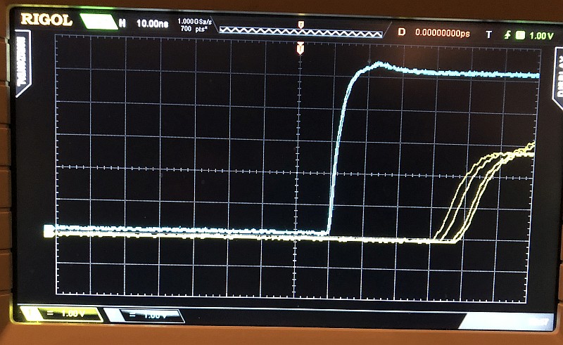 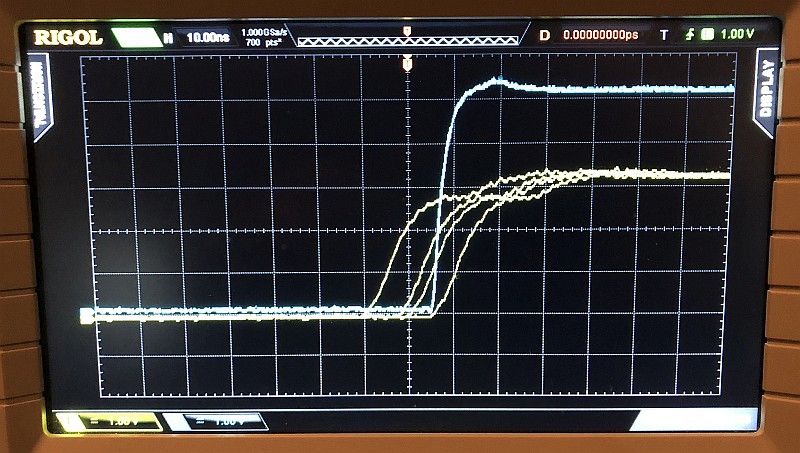 ------------- QXStuart San Francisco Bay Area |
| [top] | |
| QxStuart | Posted: 19 Jan 2020, 03:25 AM |
|
Member Posts: 10 Joined: 13-January 20 |
I just used an iPhone and a mirror behind the clock to take these 'photos' showing centisecond roll-over at GPS PPS. iPhone configured to do 240 fps Slo-Mo. 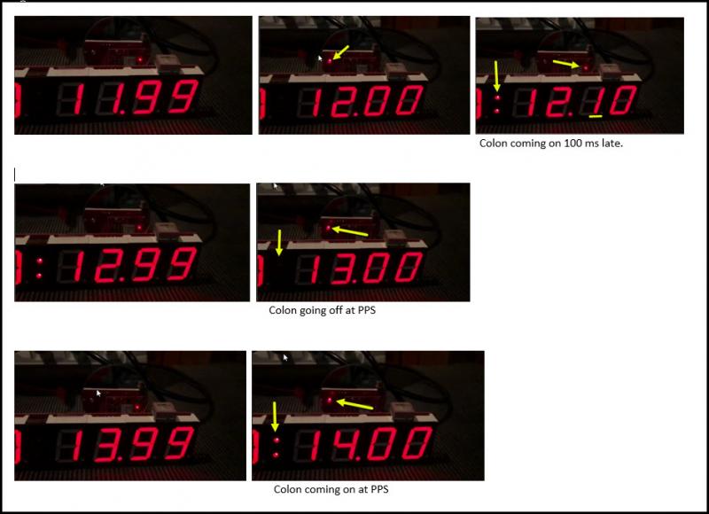 I tried scoping the colon LED voltage, but LED driver multiplexing made a mess of the scope trace. However, I could observe the 100 ms variations in the colon / timer period modulations. This is a very cool clock! ------------- QXStuart San Francisco Bay Area |
| [top] | |
| schertza | Posted: 19 Jan 2020, 05:54 PM |
 Member Posts: 5 Joined: 19-January 20 |
First off: Thank you so much for designing, building, selling this precision clock kit. I'm elderly at 60 and have acquired an neurological condition and makes my hands shake. In my youth (and mid life) I was an electronic technician with excellent soldiering skills. In the second half of my life I switched to software as a profession and placed the soldering irons in the closet. This kit gave me a chance to see if I could still do it. This kit is first rate and demonstrates how far we have come in small batch electronic kits. (at least since the Heathkit kits I was exposed to in the 1970's) I was able to assemble everything in about an hour and a half. I felt all things fit and on startup here are my findings: The tens digit of the seconds display did not light the top segment. I also noticed that other 3 digits to the left of the tens digit (seconds), were brighter than the other segments of those same digits. If I maximized the interior lights in the room (requiring more brightness via the LDR), then the top segment of the tens digit of the seconds segment would illuminate and the others top segments would be balanced with all other segments to the left. but if the lighting returned to my preferred "dim" lighting, the segment would not display correctly. I did try to adjust the pot to see if that would help but to no avail. Also when inside the time would never display. I felt this may be a GPS reception issue. So I plugged the clock into an outside outlet and after about 10 minutes the clock displayed the time. yea! But the colons never flashed and the GPS fix indicator never came on. I left it outside for over 4 hours with no flashing colons or no GPS fix indicator blinking. I assume the GPS fix indicator should flash each second. I tried reviewing all my soldering and the all look basically better than average, so I'm not so sure what to do. Open for suggestions! Thanks you for the nicely created project. Really want this to work indoors. Any suggestions on why the segments seem to not fire when in relatively dim room light? I have tried multiple power supplies, but always the same behavior. thanks, Alan Last edit by schertza at 19 Jan 2020, 06:07 PM ------------- |
| [top] | |
| QxStuart | Posted: 19 Jan 2020, 07:47 PM |
|
Member Posts: 10 Joined: 13-January 20 |
Alan, I solved similar weak signal issues, as described earlier in this thread, by purchasing this ACTIVE antenna. 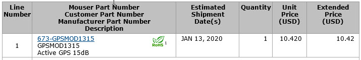 But while you wait for its arrival, try leaving the clock outside, for AT LEAST 6 HOURS, where is can see the most sky. You can power it with a USB battery if you have one. It only draws about 50 mA. Any 'fresh' GPS receiver takes that long to update their Satellite Almanac. Also assures it has determined your exact Lat/Long location for quicker start-up. Then place it inside on a windowsill with a good view of the sky. Hopefully it should lock-in again within a minute or two. Now you can move it to other indoor locations (via battery or extension cord) and note where the PPS LEDs stop flashing. The Active Antenna will make a huge improvement, but you may still have problems under a metal roof, metal foiled insulation, or multiple stories, unless near a window. John ------------- QXStuart San Francisco Bay Area |
| [top] | |
| mit | Posted: 20 Jan 2020, 02:32 PM |
|
yeah whatever Admin Posts: 687 Joined: 4-May 16 |
Alan, thanks for the kind words and I'm sure we can get your clock working. The dim segments do seem to suggest soldering problems. The digits are driven with constant current so that can manifest in interesting ways if the solder joints are high resistance. You can shine a torch on the LDR for quickly testing - so my first suggestion would be to investigate the joints on the affected digits, and then also the joints on the display driver for those digits. It's quite hard to resolder the display driver at this point, but it may be enough to add more solder from the side you can get to. It does sound like the active antenna is a big improvement, I'll hopefully have a chance to try one out soon and I may even start including them in the kit, perhaps as an optional extra. Great work with those measurements, John. The results are really impressive, to be honest I've been sceptical of the claimed accuracy of the uBlox modules. It's amazing how good they are when you remember they're nearly 100 times cheaper than the 10MHz references. If you wanted, you could adapt the clock to make use of the more stable PPS, to eliminate the jitter, but since the display is matrixed with a period of about 3ms, there wouldn't be much point. I do have a plan to build an even better clock, with no matrixing, so that every segment of every digit is displayed with microsecond accuracy. Still under development at the moment though. ------------- |
| [top] | |
| schertza | Posted: 20 Jan 2020, 10:26 PM |
|
Member Posts: 5 Joined: 19-January 20 |
Today the clock located a fix and the colons are flashing! I'm so excited. Also the top segment of the tens second digit seems to work fine during the day. I think this is due to the fact that I have placed the clock directly on my window sill hoping to maximize reception. The additional light from the window seems to "bump up" the display "inducing" the segment that does not want to fire when the room light is low. My active antenna will arrive on Wednesday and I will be sure to share my finding. Thanks John for the suggestions! I did try to do some front side soldering on the drivers. Any suggestion on which leg might need attention to help with the top segment of the fourth digit from the right. I should review your design document to figure it out, but I also thought I just might ask too. Thanks again for the awesomeness! take care John and Mit! Happy new year to both! ------------- |
| [top] | |
| mit | Posted: 21 Jan 2020, 08:56 AM |
|
yeah whatever Admin Posts: 687 Joined: 4-May 16 |
Here's a screenshot which might help. This is looking at the back of the clock, behind the seconds display. The red layer highlights the cathode of the ten-seconds digit, the green layer highlights the top segment signal. 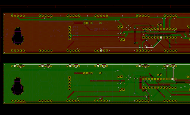 Of course it's possible the digit is faulty, in which case I can always send you more, although it's a real pain to desolder the old one from the PCB. ------------- |
| [top] | |
| schertza | Posted: 23 Jan 2020, 08:25 AM |
|
Member Posts: 5 Joined: 19-January 20 |
Tim, I just now noticed your reply of which traces had to do with segment A. (top segment) Thank you! I was able to glean this information from your previous documentation as well. So earlier in the day I checked inspected as well as "reflowed the solder" for those connections. The problem persisted. The tens digit "segment A" would not light, the the rest of "segment A"s on the other time digits were brighter than the rest of the display. I had ordered additional display digit(s) from amazon and received them. I also ordered a solder "sucker" to help with removing the tens digit of time. The solder sucker is still enroute. I did try to remove the digit via just my soldering iron without success. Then it hit me: Why not just use side cutters to "cut out" the tens digit? this was quite easy from both sides! I was able to remove the tens digit of the time display. once I removed the digit, I was able to also remove the remaining soldered leads with heat and needle nose pliers. Although the holes are not totally clean of solder so I can not yet add back on my new display. Tomorrow my solder sucker should arrive to compete the solder removal. and then allow the installation of the new display. But in the meantime I'm just running the clock without the tens digit of the time display. I strangely am not missing the info for the fact the rest of the digits luminosity are balanced. I'm happy! Thank you Tim for your awesomeness and willing to help me out. I did order another clock just for the fact I wanted it all to work. But I think I will be able to get this one working, so my second one can go to a good friend. I also have found great satisfaction in using the 15db active antenna. (from mouser) I think I can now place the clock in any room of my single story home and it retains its fixed state of "flashing" colons. thanks to John @ QxStuart as well I am truly thankful for your work Tim on this kit. This world needs more of you! Thanks again! alan Last edit by schertza at 23 Jan 2020, 08:29 AM ------------- |
| [top] | |
| QxStuart | Posted: 24 Jan 2020, 01:40 AM |
|
Member Posts: 10 Joined: 13-January 20 |
I thought I'd share these fascinating graphs of how the u-blox GPS receiver's PPS dithers back-n-forth relative to a $$$ Jackson Labs Fury GPS's PPS. I'm using a 15dB active antenna on the Precision Clock, located indoors away from windows, i.e. ~20% of outdoor signal strength. I would expect these Time Interval measureents to be more stable outdoors with more GPS satellites visible. 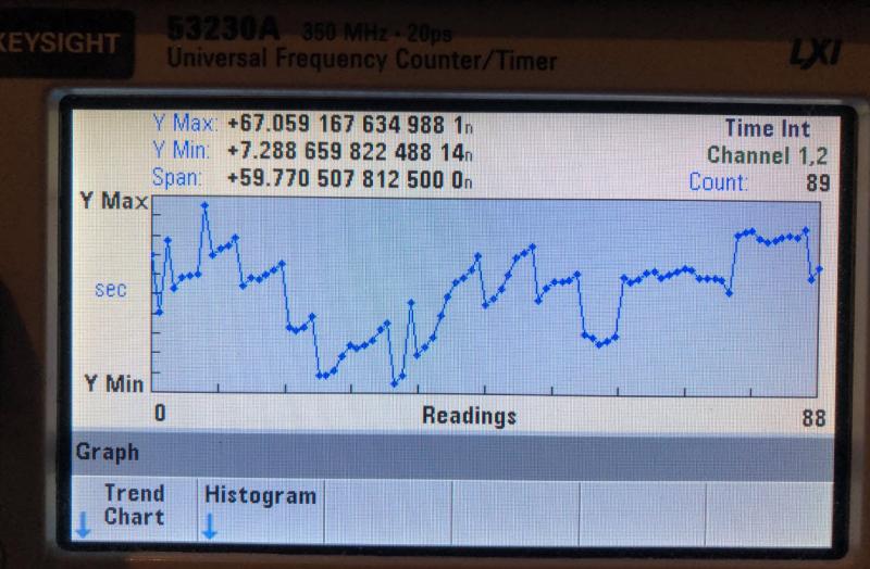 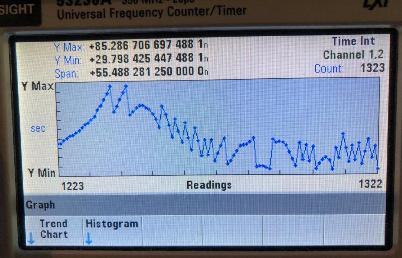 The Readings are measured every second, and yes, the "n" units are in nanoseconds! (Nanoseconds are the 7th digit off the right end of the Precision Clock !) The random-like changes in the trend can be explained by frequent changes in the constellation (group) of GPS satellites used each epoch to calculate when the PPS should occur. John San Francisco Bay Area ------------- QXStuart San Francisco Bay Area |
| [top] | |
« PreviousPages: 1 [2]
Sign in to post a reply.