
| paxman101 | Posted: 1 Jan 2020, 09:51 PM |
|---|---|
 Member Posts: 8 Joined: 1-January 20 |
Issues: 1) No Sync of time. 2) faded segment on Day Details: 1) No Sync of Time See photo attached. Steps taken to resolve: - reseated antenna - left outside for 2hrs direct vision to sky 2) Faded Segment See photo Even with full brightness, the lower right segment is just not as bright. if I cover the sensor, it really is apparent (as in this photo) Steps Taken to fix: - re-soldered the connections on the faulty segment 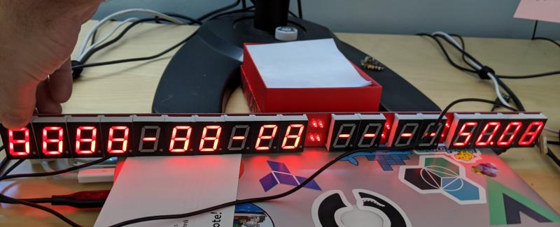 Last edit by paxman101 at 1 Jan 2020, 09:57 PM ------------- |
| [top] | |
| paxman101 | Posted: 1 Jan 2020, 09:56 PM |
|
Member Posts: 8 Joined: 1-January 20 |
update: happy new year. ------------- |
| [top] | |
| mit | Posted: 2 Jan 2020, 11:10 AM |
 yeah whatever Admin Posts: 687 Joined: 4-May 16 |
Hi, No sync - this could be a number of things, but a couple of people have had trouble with the antenna. I think it's very easy to damage the connector, or maybe it arrived damaged. I would recommend, if you have a USB-serial adapter, to try listening in on the GPS output signal. You just need to link up ground and TX from the GPS to RX on the USB-serial. Looking at the output will immediately tell you if the antenna is the problem or if it's something else. I can give you more help with this if you need it. Faded segment - hard to tell from the picture, is it just the one digit that has a problem? I'd guess that the digit is faulty. I don't recognise your username, is this one of the kits that I shipped out or are you building it from scratch? If it's one of my kits send me an email and I'll post some extra bits to you. ------------- |
| [top] | |
| paxman101 | Posted: 2 Jan 2020, 08:36 PM |
|
Member Posts: 8 Joined: 1-January 20 |
it's one of your kits, I'll email you once I get data off the GPS chip. ------------- |
| [top] | |
| paxman101 | Posted: 3 Jan 2020, 10:35 PM |
|
Member Posts: 8 Joined: 1-January 20 |
Got the USB Serial adapter.... perhaps I am an idiot.. but here is the terminal output. pictures attached also showing my setup. just to verify, could you tell me which pins on the GPS go to which pins on my breakout? Serial output, 9600 8N1 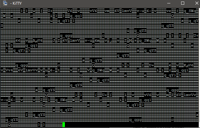 breakout board and usb to serial 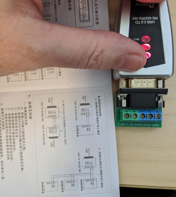 the carnage 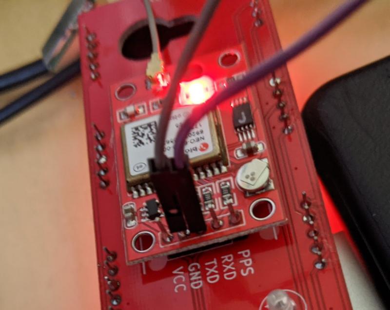 ------------- |
| [top] | |
| paxman101 | Posted: 3 Jan 2020, 10:48 PM |
|
Member Posts: 8 Joined: 1-January 20 |
While fiddling around with the tx/gnd connectors I shorted them I think by accident. but now the correct time shows up. faded segment is still faded. 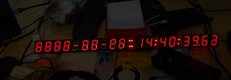 ------------- |
| [top] | |
| mit | Posted: 4 Jan 2020, 01:15 AM |
|
yeah whatever Admin Posts: 687 Joined: 4-May 16 |
If you've got junk appearing that suggests the wiring is OK. 9600, 8N1 is correct but the GPS unit is using TTL voltage levels, RS422 and RS485 use differential and/or negative voltages so to use that adapter I think you'll need a level converter. Either that or you can get a cheap FTDI clone USB-serial that expects TTL voltages. I'm more concerned that the date side of the display is still just showing 8888... It might be that the display driver is damaged. Or it's possible that the GPS chip got just a hint of a signal, enough for the time and not the date, this does occasionally happen when it's first booting up. If you do get the serial working, you should see something like: $GPGGA,141348.300,,,,,0,0,,,M,,M,,*40 ------------- |
| [top] | |
| paxman101 | Posted: 5 Jan 2020, 05:37 PM |
|
Member Posts: 8 Joined: 1-January 20 |
I got data from the GPS.. no idea what I am looking at here. will email you the results because I think is has my home information in it. Last edit by paxman101 at 5 Jan 2020, 05:38 PM ------------- |
| [top] | |
| paxman101 | Posted: 6 Jan 2020, 06:59 PM |
|
Member Posts: 8 Joined: 1-January 20 |
the issue was the damn display driver furthest from the GPS chip. I first tried to desolder the digits that were blocking the underside of that chip, but I gave up, desoldering is annoying AF. so I just slagged a ton of solder from the other side, and that fixed the issue. I still have one bad digit (the faded one) but if I crank the brightness to full, the missing segment lights up. fun project, now to get some smoked glass and a frame for it. ------------- |
| [top] | |
| mit | Posted: 7 Jan 2020, 01:03 PM |
|
yeah whatever Admin Posts: 687 Joined: 4-May 16 |
Excellent, glad you got it working. Yeah desoldering is a pain, the best way is to use a heat gun and have a lot of patience. I'm wondering how many other clocks might have bad segments, I think we only noticed because the display driver wasn't working. Maybe I need to add a "display test" mode. ------------- |
| [top] | |
| paxman101 | Posted: 12 Jan 2020, 09:26 PM |
|
Member Posts: 8 Joined: 1-January 20 |
A test suite of some sort that uses the GPS lock light (which is redundant) would be awesome. For me, It would have been great to have a 'test' stage after I populated the chip side of the board, before attaching all the digits. Solid Lamp: All good Blink once: you got a bad display driver Blink twice: you got a GPS issue Blink three: you dun messed up and its better to bin the whole project because you really should not be allowed to hold a soldering iron and drink beer at the same time. ------------- |
| [top] | |
Sign in to post a reply.