
| BlahDehBlah | Posted: 5 May 2022, 04:47 PM |
|---|---|
 Member Posts: 2 Joined: 5-May 22 |
I just finished the clock and fired it up. The GPS got its fix within a few minutes with both the on-module and onboard LED blinking every second. Besides that, there is no activity. I was worried I soldered in a chip backwards but there was no heat coming from any of them and they're all seated properly. This is my first solder project so I can't rule out any other silly mistakes y'all can think of. 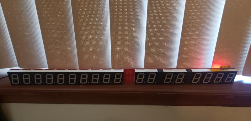 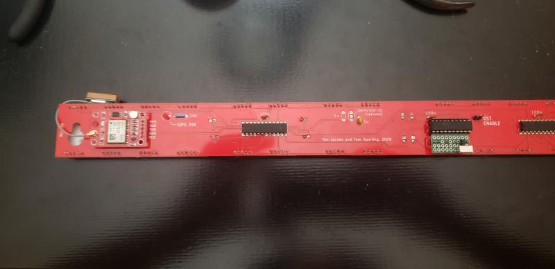 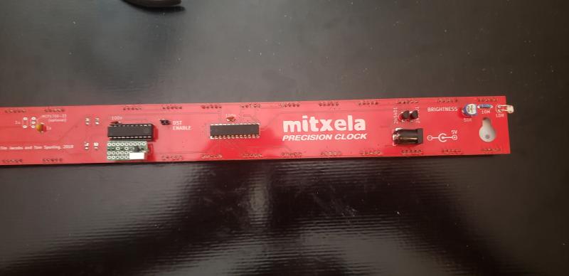 P.S. I double checked the trim pot, it's not that! ------------- |
| [top] | |
| mit | Posted: 6 May 2022, 09:26 AM |
 yeah whatever Admin Posts: 687 Joined: 4-May 16 |
Hi, I assume this is a recent clock kit, but just to confirm, clock kits that shipped on 13th Jan 2021 were sent with faulty display driver chips. I sent a mass email and put a note on the instructions, but not everyone got back to me. Since then, I have tested every display driver chip before shipping. The first thing I would check is the continuity for the SPI data between the ATtiny and the display chips. If you have a multimeter, use the continuity tester mode, and just check that there is good connection between the pins. The SPI_CLK line is highlighted in this screenshot: 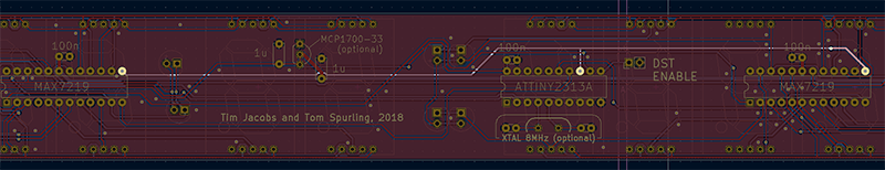 There is also an interactive schematic here: https://mitxela.com/img/uploads/clock/mk3/clock3-bom.html If either SPI_DATA or SPI_CLK aren't connected, that could explain it. If the SPI is all good, then the problem might be with the brightness circuit. If no current enters the ISET pins then the display will be completely dark. Again, check the continuity if you can. It may be possible to override the brightness circuit temporarily by poking the pins of a display chip with a resistor (say 10k or 20k). Putting it between the iset pin and the adjacent 5v pin should at least get the display to show something, if that's what the problem was. These two pins: 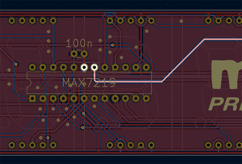 Apart from that, it could be that the ATtiny chip isn't powering up. Maybe (for instance) a soldering mistake is grounding the reset pin. I suppose there are lots of things it could be. The board looks fine in the pictures you posted, but if you can get some closeups of the soldering I might be able to spot something. ------------- |
| [top] | |
| BlahDehBlah | Posted: 22 May 2022, 07:28 AM |
|
Member Posts: 2 Joined: 5-May 22 |
Sorry for the (very) late reply I checked for continuity between the provided test points as well as the 5v and ground pins between all the chips and the power jack. All looks good there. From there I checked voltages with the board powered. All chips are receiving a rock solid 5v but pin 1 of the attiny is indeed grounded which is perpetually resetting it. I'll report back once I've resoldered the socket. ------------- |
| [top] | |
Sign in to post a reply.