
| FabiSahne | Posted: 17 Sep 2020, 10:23 PM |
|---|---|
 Member Posts: 4 Joined: 17-September 20 |
So, I just assembled my clock and plugged it in a 5V outlet. In the assembly guide it said it takes a while for it to get a fix so I waited. After a few minutes I checked on it and the GPS module and the GPS fix LED was blinking, but the clock still showed "-------- --:20:65.45" (more or less) and counting. ------------- |
| [top] | |
| mit | Posted: 18 Sep 2020, 08:06 AM |
 yeah whatever Admin Posts: 687 Joined: 4-May 16 |
That suggests the serial data isn't making it from the GPS module to the ATtiny chip. It is probably a soldering error somewhere. If you have a multimeter, check continuity between the GPS module's TX pin and RXD on the ATtiny, which is pin 2. 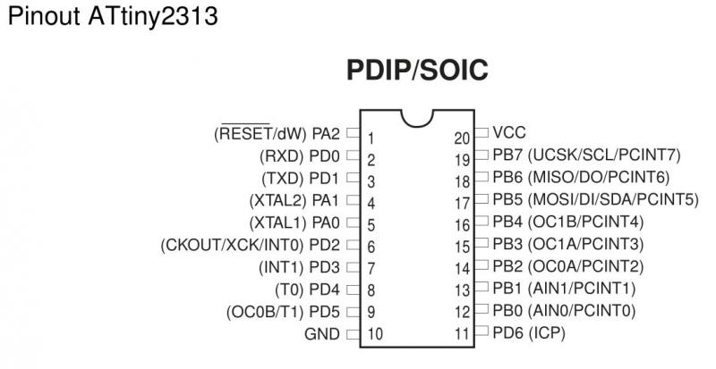 If it does turn out to be a soldering problem, it will be quite tricky to fix, because the digits are now in the way.I would suggest confirming this is the problem before going any further, perhaps using a wire to directly touch the ATtiny's RX pin to the GPS module's TX. If you hold it there for more than a second, the time should suddenly appear. One other question - while the clock is sitting there counting, are the seconds ticking at about the right speed? If it's ticking much faster or much slower than real-time, that could be a problem with the chip itself. ------------- |
| [top] | |
| FabiSahne | Posted: 18 Sep 2020, 02:12 PM |
|
Member Posts: 4 Joined: 17-September 20 |
No, GPS TX and AT-Tiny RX have continuity. And yes the seconds tick at about the right speed ------------- |
| [top] | |
| FabiSahne | Posted: 18 Sep 2020, 08:37 PM |
|
Member Posts: 4 Joined: 17-September 20 |
Now that I had a closer look at it, the seconds do in fact tick at the exact time the GPS Led blinks. Last edit by FabiSahne at 18 Sep 2020, 08:37 PM ------------- |
| [top] | |
| mit | Posted: 18 Sep 2020, 09:08 PM |
|
yeah whatever Admin Posts: 687 Joined: 4-May 16 |
OK, there are a couple of things it could be. It still might be a soldering error, if the pin is accidentally shorted to ground or vcc, it would have continuity but not transmit the data. If you have an oscilloscope or a USB-serial adapter, it would be possible to check if the data is there. Another thought has occurred to me though, if this clock kit was shipped near the start of August it may be one of a small batch that were mis-calibrated. I'm not sure if it could be so far out as to not get the time or any data at all, but it's possible. If you think this might be the case, one way of checking would be to warm up the ATtiny chip a bit. The oscillator is temperature dependant, so heating it up to about 35°C should be enough. If the clock starts working when the chip is heated, that would confirm it, I can either send you another ATtiny or give instructions on how to fix this. But again, it would have to be very far out of calibration to not receive any data, usually it just results in junk being displayed. ------------- |
| [top] | |
| FabiSahne | Posted: 18 Sep 2020, 10:29 PM |
|
Member Posts: 4 Joined: 17-September 20 |
Sadly, I don't have an Oscilloscope or an USB-Serial adapter. But I probed around with my multimeter a bit more, but I'm still a noob when it comes to stuff like this so I will need a bit of help interpreting its readout. GPS TX - ATtiny RX = Continuity Beep GPS TX - GND = a small voltage with a diode symbol? GPS TX - VCC = also a small Voltage with a diode symbol... My Multimeter was set to Continuity, but there is also a diode symbol. Edit: The kit was purchased early September. Last edit by FabiSahne at 18 Sep 2020, 10:34 PM ------------- |
| [top] | |
| mit | Posted: 19 Sep 2020, 08:08 AM |
|
yeah whatever Admin Posts: 687 Joined: 4-May 16 |
Hmm, those readings sound fine. I will have to think about what else could be the problem. I double-checked the calibration on all the kits posted in September so far. If you can get hold of a USB-serial adapter, it will make debugging easier. An FTDI clone like this costs about 5 euros: 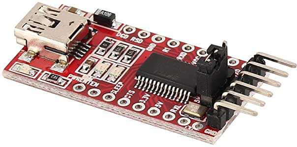 That will let you read the data coming off the GPS module. Just connect the ground wire and the TX on GPS to the RX on the FTDI. A serial monitor program like PuTTY, minicom, or the one built into the Arduino IDE would work. The baud rate is 9600. If you do read out some data, be aware that it'll have your GPS location in it, so you may not want to post it all here. ------------- |
| [top] | |
| mac_ron | Posted: 9 Oct 2020, 08:10 AM |
 yep yep yep Member Posts: 6 Joined: 9-October 20 |
Good morning Alex and FabiSahne! I have just received a new precision clock yesterday (thank you Alex for the quick delivery!) and instantly put it together. Basically, I would say I'd have the very same issue here. The clock needs about five to ten minutes, then indicates GPS fix, but still does not display date or time (only the initial counter continues to run). I also do not see a soldering issue here, connection between GPS module and ATtiny seem to be fine for me. But: I do have an oscilloscope and did measure the communications between TX and RX ports. I just left everything soldered as is and connected the probe to GND (antenna plug housing) and TX pin of the GPS module. Firstly, I did see a signal every second (corresponding to the blinking GPS fix LED). At 9600 baud (8 bits, 1 stop, no parity) the oscilloscope was in fact decoding some data, I found some NMEA data strings (or at least fragments as you can see in the attached screenshots). You can see the fragment of an accurate UTC timestamp in the third image („071615“). Does this help in any way? Kind regards, Ron.     ------------- |
| [top] | |
| mit | Posted: 9 Oct 2020, 04:41 PM |
|
yeah whatever Admin Posts: 687 Joined: 4-May 16 |
Hmm. So data is fine, and is definitely reaching the chip? Aside from soldering/continuity errors I'm not sure what it could be. I guess it's possible the GPS module is running a different firmware which doesn't report $GPRMC, the message the clock is waiting for. On the scope, keep a look out for it. I'm pretty sure every version of the GPS module reports $GPRMC but it's possible I'm wrong. There's a remote possibility the ATtiny chip isn't working. Unlikely, because I manually tested every chip sent out. I will have a think about what else it could be. It could only really be either the GPS module, the ATtiny, or the connection between them... ------------- |
| [top] | |
| mac_ron | Posted: 9 Oct 2020, 05:01 PM |
|
yep yep yep Member Posts: 6 Joined: 9-October 20 |
Hi Tim! Thank you for your thoughts! As for the missing $GPRMC, as it is the „Recommended Minimum Sentence“, I doubt it would be left out. I will copy the whole data stream within the next few days and additionally de-solder the respective LED digits to also double-check the soldering from and to the ATtiny. I guess the GPS module starts firing its broadcast right after powering it with 5 V, correct?! So I can check it apart from the clock first and connect it to an FTDI board instead. Cheers, Ron. ------------- |
| [top] | |
| mit | Posted: 9 Oct 2020, 05:19 PM |
|
yeah whatever Admin Posts: 687 Joined: 4-May 16 |
Yes, it starts reporting right from power-on. There are a few TXT messages at the start, then the rest of the NMEA data starts streaming out, with unknown fields left empty. If you get the FTDI board you can listen in on the serial data without needing to disconnect the module. So long as the grounds are connected, the FTDI's RX pin can listen in on the data while the clock is running. ------------- |
| [top] | |
| mac_ron | Posted: 9 Oct 2020, 05:22 PM |
|
yep yep yep Member Posts: 6 Joined: 9-October 20 |
OK, thank you! Will report next week. Cheers, Ron. ------------- |
| [top] | |
| mac_ron | Posted: 17 Oct 2020, 09:56 AM |
|
yep yep yep Member Posts: 6 Joined: 9-October 20 |
Hej Tim! It took a bit longer to grab an FTDI interface, but in the meantime I used the time to re-solder all ATmega pin connections as well as the GPS module pins — without any change. All soldering connections definitely were and are perfect. Now I have captured the GPS sentences as follows: QUOTE
$GNGGA,094203.686,,,,,0,00,25.5,,,,,,*7E The time was 11:42 CEST, so 9:42 UTC. So what we can indeed conclude here is that this particular GPS unit does not report a $GPRMC sentence, but a $GNRMC instead. Whatever reason this change may be good for ... If you could change the code accordingly (I could not find the string „GPRMC“ within the GitHub repo) or advise where to change the code, this would be appreciated. Kind regards, Ron. ------------- |
| [top] | |
| mac_ron | Posted: 17 Oct 2020, 09:59 AM |
|
yep yep yep Member Posts: 6 Joined: 9-October 20 |
... Ah, found it. It's coded bytewise. Line 771 if I am right. Would it be suffice to change that line of code accordingly? Cheers, Ron. ------------- |
| [top] | |
| mit | Posted: 17 Oct 2020, 12:12 PM |
|
yeah whatever Admin Posts: 687 Joined: 4-May 16 |
Oh dear... thanks for discovering that. Looks like GPRMC and GNRMC have the same fields, so changing the 'P' to a 'N' on line 771 should indeed fix it. But really the logic should be changed so it can work with either. Seems like "$GN" strings refer to GLONASS satellites, or a combination of GPS and GLONASS. "$GL" is also apparently a possibility. So perhaps the best option is to simple comment out line 772, and ignore whatever value is at that position. If it's not too much trouble, would it be possible to capture the text output at the very beginning, during power up? There should be a few TXT fields that list the module's firmware. ------------- |
| [top] | |
Sign in to post a reply.