
| jonas | Posted: 29 May 2025, 03:47 PM |
|---|---|
 Member Posts: 8 Joined: 29-May 25 |
Hello everyone, sent an e-mail to Tim, but in the meantime I discovered this wonderful forum and wonder if anyone can help me. I’ve managed to source all the parts for the latest Precision Clock, get a pcb made, build and program it. It shows time, gets GPS lock – all good. But I cannot manage to set the brightness to my liking. Admittedly, I used white LEDs and segments (link bellow) instead of red and they might be drawing more current – but I assumed I’ll be able to just fiddle around with setting up the Iset current at the segment driver. No luck. I removed the LDR and minimum brightness resistor to be sure and when I adjust the Rset (pot) to some lower values (10k), the dot in the seconds part gets brighter and digit next to it dimmer, but nothing else – and the date starts to flicker. I added some extra electrolytic capacitors near the segment drivers to help with the flicker, but no matter how hard I try I am unable to get the digits brighter. Thanks for any suggestion! Displays: https://www.tme.eu/Document/d6eff7100a3586906aec297d63b23112/OSL11004-LW5.pdf 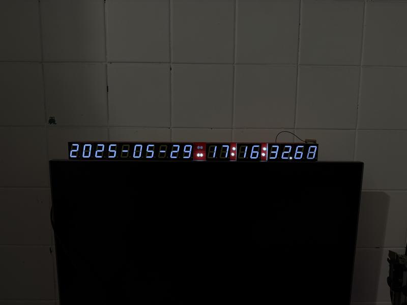 Last edit by jonas at 29 May 2025, 03:49 PM ------------- |
| [top] | |
| mit | Posted: 29 May 2025, 04:22 PM |
 yeah whatever Admin Posts: 687 Joined: 4-May 16 |
Hi - the datasheet for those digits shows they have two LEDs in series for each segment: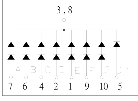 Since they're white, the forward voltage for the segments ends up as 6.2V, which the MAX chips can't drive (as they're powered from 5V). You might be able to get away with slightly over-voltaging the clock, but you'd probably need to get a bit higher than 6.2V to drive them as there'll be the transistor drop too. I think going higher than 6V will fry the driver chips. Unfortunately, the only solution is probably to replace the digits with ones that have a single LED for each segment. ------------- |
| [top] | |
| jonas | Posted: 29 May 2025, 04:39 PM |
|
Member Posts: 8 Joined: 29-May 25 |
Makes complete sense, I missed that part! Thank you ------------- |
| [top] | |
| mit | Posted: 30 May 2025, 08:12 AM |
|
yeah whatever Admin Posts: 687 Joined: 4-May 16 |
I'll add a note to the instructions page to watch out for digits with multiple LEDs in series, I wasn't even aware they were available in this size. For desoldering digits, the absolute best way is with a spade bit soldering tip, a T12 spade tip that fits the TS101 is only about £10 on aliexpress: 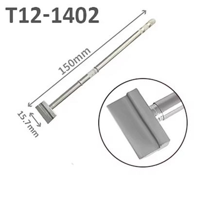 Alternatively a more generic desoldering tool will work fine, and also maybe be more useful in other situations compared to a specialist tool like this. ------------- |
| [top] | |
| jonas | Posted: 2 Jun 2025, 12:51 PM |
|
Member Posts: 8 Joined: 29-May 25 |
thanks! One more question – there is no spec for the LDR. They come in different ranges, on tme.eu I for example see 2÷5kΩ, 150÷300kΩ... what is the one you used in the kit? oh and some feedback for the build guide, if you ever feel like updating it (I know that not so many people will build it after the IV release): – from my experience it is easiest to solder components in order of their height – that way the gravity pushes the circuit board nicely against them when flipped. your order didn’t make some obvious sense to me (but I might be missing something – i used precision sockets for all ICs - it is only marginally more expensive – standard ICSP header on the board would make things easier programming wise – I would add extra e-lytic caps just for general stability – not all USB PSUs are equally clean thanks again for doing this project! so much fun ------------- |
| [top] | |
| mit | Posted: 2 Jun 2025, 01:24 PM |
|
yeah whatever Admin Posts: 687 Joined: 4-May 16 |
The LDR was normally GL5528, but you can adjust to different LDRs by varying the 50K trimpot and the 10M resistor for max and min brightnesses. The feedback all sounds valid, yeah I think I probably would have added all of that if I were doing another revision of it. ------------- |
| [top] | |
| jonas | Posted: 12 Jun 2025, 11:02 AM |
|
Member Posts: 8 Joined: 29-May 25 |
Thanks a lot! I have one more curious question – I am digging through the assembly code – it has been a while since I did asm so please bear with me. I would like to modify it to show the GPS time instead of the UTC time, so – without leap seconds. But I cannot find where exactly this happens within the code. ------------- |
| [top] | |
| mit | Posted: 12 Jun 2025, 11:29 AM |
|
yeah whatever Admin Posts: 687 Joined: 4-May 16 |
The leap second offset is applied on the GPS module. The NMEA strings conveniently output (or try to output) UTC directly. It's possible to extract more detailed info depending on what GPS module you're using, if it's a u-Blox module there is the UBX protocol. Looks like the UBX-NAV-TIMELS message gives you the GPS/UTC offset. But working with that on the Mk III clock is going to be difficult. ------------- |
| [top] | |
| jonas | Posted: 13 Jun 2025, 09:08 AM |
|
Member Posts: 8 Joined: 29-May 25 |
understood! thanks I am using u-blox NEO-M8N... but as you said, seems complicated to add :) I was thinking maybe I could define a virtual time zone that would allow me to do that (introduce the necessary +18 second shift), but it only allows for hours and minutes shift, correct? ------------- |
| [top] | |
| mit | Posted: 16 Jun 2025, 01:32 PM |
|
yeah whatever Admin Posts: 687 Joined: 4-May 16 |
Yes, the MK III can only do hours and minutes shift. The Mk IV can do any number of seconds offset, if defined in the rules file. ------------- |
| [top] | |
Sign in to post a reply.