
| j4cobgarby | Posted: 21 Feb 2021, 06:44 PM |
|---|---|
 Member Posts: 2 Joined: 21-February 21 |
I'm making a microcontroller draw a game on an oscilloscope's screen, using vector graphics, and then came across the similar project (https://mitxela.com/projects/console) here. I'm having an issue with my one, where basically because the X and Y positions of the dot on the screen are set by the microcontroller at slightly different times, diagonal lines are instead drawn as two horizontal lines, "stepping" from the beginning to end position. I'm looking at the circuit diagram for the game console at the above link, and can't work out how it gets around this issue. One idea I had was to move from one position to another in many steps, but I think this takes away from the point in vector graphics, and also increases processing time. However I implemented this and it sort of works. I'll attach an image of the oscilloscope trying to draw a triangle, as well as the waveforms of the signal drawing it (X at the bottom, Y at the top.) 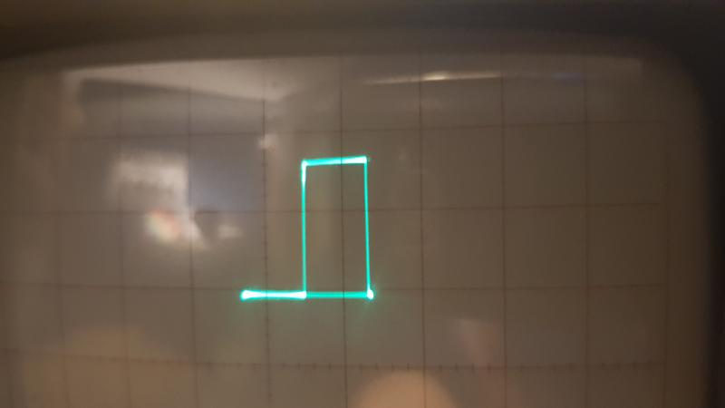 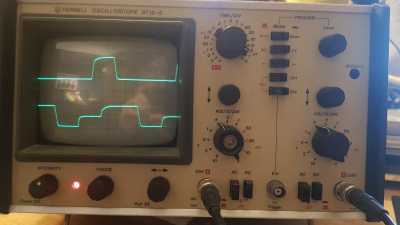 ------------- |
| [top] | |
| mit | Posted: 22 Feb 2021, 01:44 PM |
 yeah whatever Admin Posts: 687 Joined: 4-May 16 |
The "slew rate" is the max speed that the output voltage can change at. In my case it was 13 volts per microsecond, which is slower than I wanted but much faster than any original vector games. On my console I also wanted to display text and sprites, in addition to vector lines, so I needed the speed to be as high as possible. But this means drawing a line is a lot harder. The algorithm to get straight lines is called Bressenham's line algorithm (there are some examples on wikipedia). Using Bressenham with a vector console is totally stupid, but the whole thing was silly anyway. What you could do is intentionally slow down the slew rate by adding a low-pass filter. Actually looking at your image again, if that's how a triangle ends up, I might be talking about the wrong thing. If the micro is running at a few MHz, then the steppiness of the shape is due to the clock speed of the GPIO or however data is sent to the DAC. My method was drawing shapes slowly, moving small amounts with bressenham and delaying at each position, whereas if you want to go round as fast as possible, maybe it would be better to build a latch circuit to ensure both X and Y update at the same time. Or, it might be enough to just slow down the slew rate and slow down the output of the microcontroller, then the relative time between X and Y updating would be negligible. I dunno. What kind of DAC are you using? ------------- |
| [top] | |
| j4cobgarby | Posted: 22 Feb 2021, 03:35 PM |
|
Member Posts: 2 Joined: 21-February 21 |
QUOTE (mit)
The "slew rate" is the max speed that the output voltage can change at. In my case it was 13 volts per microsecond, which is slower than I wanted but much faster than any original vector games. Thanks for the reply, I will try a low pass filter, I was going to try basically that yesterday but it seems I've lost my box of capacitors so I'll have to buy some new ones Oh and about the DAC I'm using -- it's actually inbuilt in the microcontroller. I'm using the teensy 3.5 (https://www.pjrc.com/store/teensy35.html), which has two 12-bit DACs inbuilt. The DACs are part of the actual processor on the board, I believe, so I don't think there should be any issue in how the data is sent to them. My current plan is to use two sample-and-holds, so I can make them hold the voltage at a certain value while I'm setting both analogue outputs, and then once they're set I can get them to sample the values. As I said above though, I will try a low pass filter first as that would be way simpler. ------------- |
| [top] | |
Sign in to post a reply.