
| 0100010 | Posted: 10 Oct 2026, 06:15 PM |
|---|---|
 Member Posts: 6 Joined: 10-October 26 |
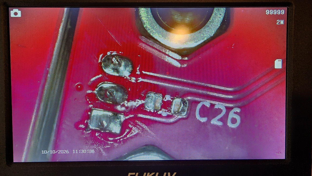
Hello, Received and assembled my MK IV Rev D clock today. Upon powering it on, it only displays a D2 ERROR, and U11 gets very hot very quickly. Per the FAQs this would indicate an inability to communicate with the left / date side of the board. But testing continuity with the 4 test pads near J3 and J4 with the flex cable in place, shows connectivity: J3-1 --> J4-1, J4-4 J3-2 --> J4-2 J3-3 --> J4-3 J3-4 --> J4-4, J4-1 My board is also missing C26 (let me get a picture). Perhaps I knocked it off during assembly? But with U11 getting hot, would suspect a short somewhere; if there is one, I have not found it yet. ------------- |
| [top] | |
| 0100010 | Posted: 10 Oct 2026, 09:51 PM |
|
Member Posts: 6 Joined: 10-October 26 |
 ------------- |
| [top] | |
| mit | Posted: 11 Oct 2026, 01:10 PM |
 yeah whatever Admin Posts: 699 Joined: 4-May 16 |
With the regulator getting hot it must be something is shorting the power rails on the date side. This is usually caused by a soldering error on the legs of the hall sensor but it might be something else. From the picture, the soldering on the legs of the sensor looks OK, apart from the missing capacitor. That's just a 100nF cap on the power to the sensor, it wouldn't be the cause of the d2 error on its own. The sensor most likely works fine without it. I suggest testing continuity between VDD and ground on the date side (checking it in both directions). There are labelled pads near the middle of the board. I would give the whole of the date side board a good look under the microscope if you can, maybe there is a stray blob of solder or something somewhere? I wonder if the capacitor was knocked off during shipping, maybe check the antistatic bags the boards were sent in? I recently had a report of a board being damaged because the package was crushed in transit. There could be other damage to the board elsewhere, if that's the case. The best tool if you have access to it is a thermal camera, it can help spot shorts very quickly. ------------- |
| [top] | |
| 0100010 | Posted: 11 Oct 2026, 01:16 PM |
|
Member Posts: 6 Joined: 10-October 26 |
Will see if have a suitable cap to replace C26. The 3 legs on the hall effect sensor - no visible short on the back, but two of the legs have continuity. Got a part number? No thermal camera, I'll go back over the board again. ------------- |
| [top] | |
| 0100010 | Posted: 11 Oct 2026, 01:20 PM |
|
Member Posts: 6 Joined: 10-October 26 |
I did look in the bags / box / bench for the broken C26 cap, did not see it anywhere. Don't know if got knocked off in shipping, or I broke it tightening the nuts. ------------- |
| [top] | |
| mit | Posted: 11 Oct 2026, 01:25 PM |
|
yeah whatever Admin Posts: 699 Joined: 4-May 16 |
The part number for the hall sensor is DRV5032FCLPGM. The middle pin is ground, pin 1 is VDD, with the capacitor between VDD and GND. 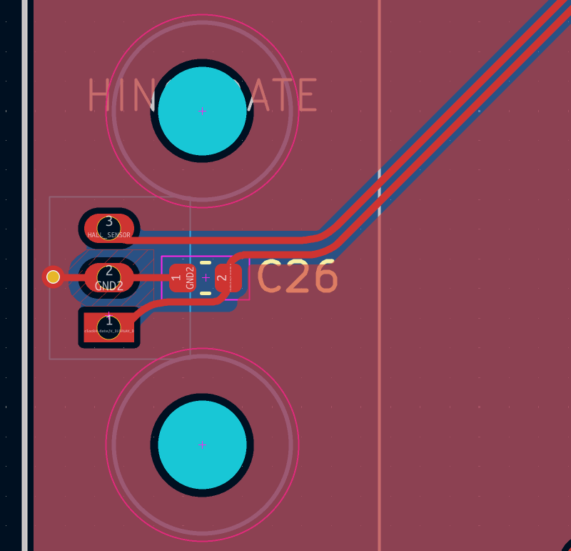 ------------- |
| [top] | |
| 0100010 | Posted: 11 Oct 2026, 01:48 PM |
|
Member Posts: 6 Joined: 10-October 26 |
Looks like it was a shaving of the leg when inserted on the front.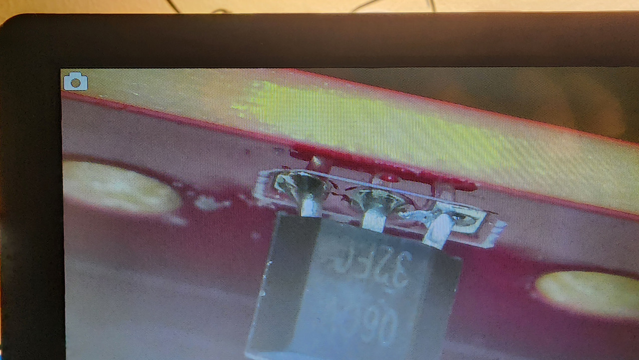 ------------- |
| [top] | |
| mit | Posted: 11 Oct 2026, 02:13 PM |
|
yeah whatever Admin Posts: 699 Joined: 4-May 16 |
Fascinating! I have not seen that happen before. It is probably a side-effect of the wider footprint, which ironically was meant to make soldering the part easier. Maybe poking it with a needle or something can break that connection without needing to completely resolder it. ------------- |
| [top] | |
| 0100010 | Posted: 11 Oct 2026, 02:31 PM |
|
Member Posts: 6 Joined: 10-October 26 |
Lol yup. That's exactly what I did. Clock works great now, I just need a better located GPS antenna. The hall effect sensor does still work w/o C26. 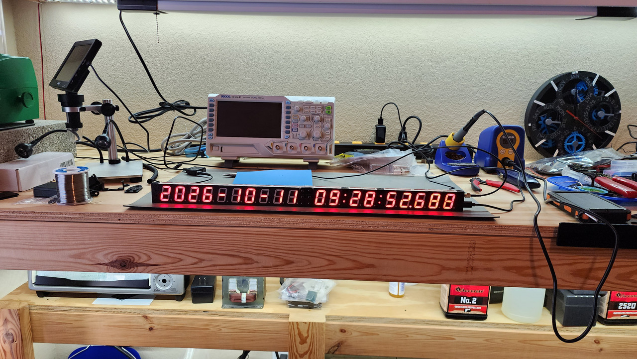 ------------- |
| [top] | |
Sign in to post a reply.