
| VonBarth | Posted: 30 Mar 2019, 01:36 AM |
|---|---|
 -]Dream Machine[- Member Posts: 7 Joined: 30-March 19 |
Hello, I ordered two of these gamepads from Alibaba for $4.60 each to go with my RetroPie: (MOCUTE 051 Bluetooth Gamepad) https://www.aliexpress.com/item/Wireless-Bluetooth-Gamepad-VR-Remote-Mini-Bluetooth-Game-Controller-Joystick-For-IPhone-IOS-Xiaomi-Android-Gamepad/32702183197.html 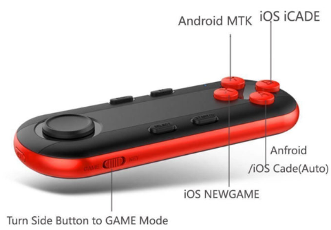 I knew it was a risk to order such cheap devices because often you get what you pay for when ordering from china, but I figured for $12.40 for two of them including shipping I would take the risk. So I have them, and they’re nice little devices and have some cool modes like iCade, Android MTK and “mouse” mode which moves the mouse onscreen, but there are some challenges when using them with Retropie / EmulationStation. The problem is they show up as “KEYBOARD” in Retropie. I did some poking around and sure enough, the HID profile is saying keyboard loud and clear. This is a non-starter, because ES (EmulationStation) can only see one keyboard at a time. This means that the controllers will always overlap keys. I even tried them in all their different modes to see if I could coax different keystrokes out of them, but no joy there. In addition they can only send one keystroke (button push) at a time, which means using ES hotkey is out of the question. If they had a "gamepad" or "game controller" mode that would be so much better. So naturally I took one apart. Inside I found a BK3231: 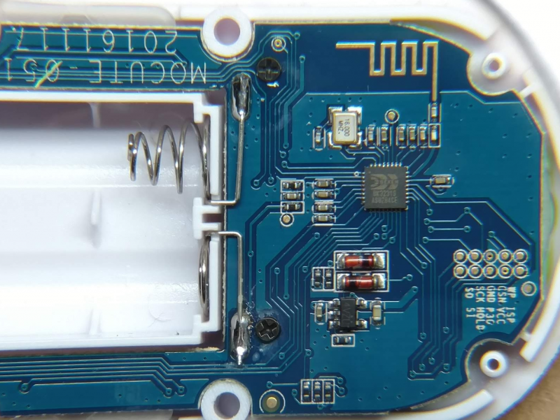 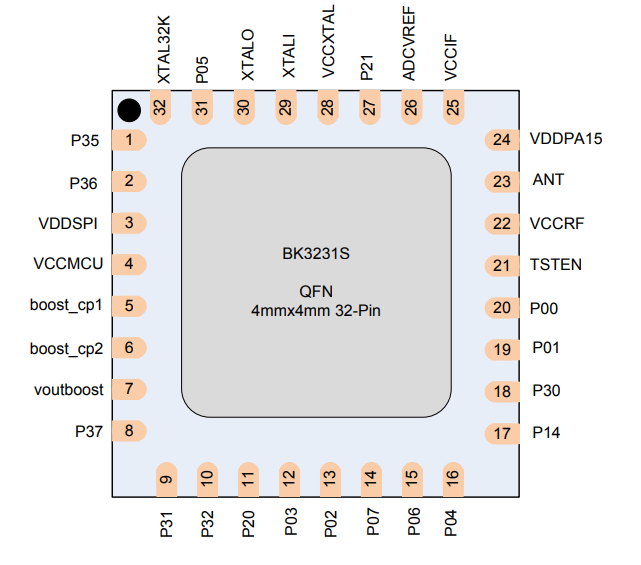 https://oss.aliyuncs.com/netmarket/f49abd45-0b36-460b-a160-e836d9da18b2.pdf It’s the only IC on the board, and quite a capable little guy, taking care of Bluetooth plus I/O for all the buttons. I thought I’d ask you guys, do you think it’s feasible to connect to the chip temporarily in order to use AT commands to alter the HID profile from Keyboard to Gamepad? I found some docs on the chip, and the AT command listing. The UART pins on the chip are P20 (TX), P21 (RX) This is my first dive this deep so I’m a little hazy on what other pin I might have to signal in order to bring it into AT mode, and I’m not sure if this is all possible. AT Commands: diwo.bq.com/wp-content/uploads/2014/11/BLK-MD-BC04-B_AT-COMMANDS.pdf p.s. mit, your “Bluetooth HID gamepad using HC-05 module” gave me the inspiration to even attempt this project, and I’ve already gone ahead and ordered an HC-05 module and FTDI serial adapter to begin work on my own custom Bluetooth controller. If I can manage to get the RN-42 firmware loaded I’ll use one of my Arduino's as a go-between the hardware and the bt module. I hope I can because designing my own controller from scratch has always been a dream of mine, so thanks for that detailed article. ------------- |
| [top] | |
| mit | Posted: 30 Mar 2019, 03:22 AM |
 yeah whatever Admin Posts: 687 Joined: 4-May 16 |
Hi. I'm not familiar with that chip but it's a System-on-Chip, which means there's a whole lot of stuff packed into one little IC. The datasheet lists an ARM core, which is great because we know the architecture of ARM processors, unlike the proprietary cores of the CSR chips. There is also a very attractive-looking labelled programming header on the board. This means that dumping or replacing the firmware should be easy, assuming there are no lock bits. There is a complete processor in that chip, and the AT-commands are only going to be listened to if the software the processor is running cares about them. It's not clear if that'll be the case. A lot of chips come with a stock firmware that listens to AT-commands, but for advanced use it's expected that the product developers will write their own firmware for the chip. If there were more components on the board - say, a host microcontroller to which the BK3231 was a slave - it would be more likely that the BK3231 was running firmware that would listen to AT commands. That's not to say that it definitely isn't, but I think it's unlikely. If you want to alter the gamepads to have better firmware, you will need to find the toolchain or SDK for that chip. Knowing that it's an ARM core is not sufficient. There will also be a more extensive datasheet available somewhere (but maybe not for free). The datasheet you've found is only 24 pages, whereas the full documentation will be a few hundred at least. It might be labelled as a reference manual, or user guide. There is also the distinct possibility that these documents are behind paywalls. I've not looked into this at all, this is just general advice. So having said all that, I would say your best bet is to alter RetroPie to work with the unmodified gamepads. With enough effort, it should be possible to make the two pads appear as different devices. It may take some linux wrangling, but at least it's open source. ------------- |
| [top] | |
| VonBarth | Posted: 30 Mar 2019, 10:35 AM |
|
-]Dream Machine[- Member Posts: 7 Joined: 30-March 19 |
Thanks for your sage advice. You’ve clued me in on a few more dimensions to this hack that I wasn’t even aware of. Namely the ARM Core, software complexity on the chip, and the extensive datasheets and/or manuals that surely exist for manufactures leveraging the chip in their devices. I’ll do some homework on those things for sure. For software solutions, I did briefly consider writing some sort of Bluetooth middleware that would intercept the keyboard controllers and remap them as gamepads somehow, but I hadn’t considered patching RetroPie. Thanks for that idea, because now that I think about it maybe I can craft something that would be an addable module to RetroPie other people could use. I’ve noticed they are really open and cool about the project. To be honest i'm more of a software guy anyways :> Also, your comment about the host microcontroller makes a lot of sense now because I found some people who created a circuit to "upload" to the chip, although it's vague what they're talking about. Maybe uploading new firmware to the chip? Anyway, interesting: https://forum.arduino.cc/index.php?topic=348546.0 https://forum.allaboutcircuits.com/threads/unknown-bluetooth-module-with-bk3231-chip.123933/ 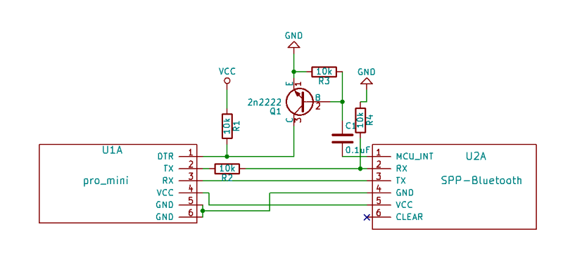 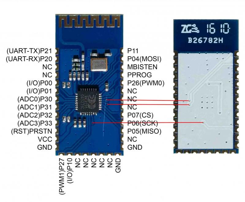 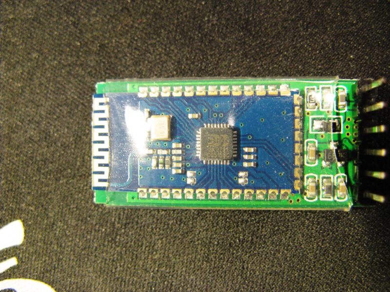 ------------- |
| [top] | |
| mit | Posted: 31 Mar 2019, 09:25 PM |
|
yeah whatever Admin Posts: 687 Joined: 4-May 16 |
Here's a potentially useful page: https://unix.stackexchange.com/questions/72483/how-to-distinguish-input-from-different-keyboards The first answer, about reading directly from /dev/input/* is what I had in mind, but the second one, about remapping one of the keyboards to give different keycodes, might be a very neat solution to your problem. ------------- |
| [top] | |
| VonBarth | Posted: 4 Apr 2019, 07:31 PM |
|
-]Dream Machine[- Member Posts: 7 Joined: 30-March 19 |
Wow nice - thanks so much! I'll give it a shot (setxkbmap) ------------- |
| [top] | |
| brainstorm | Posted: 16 Jul 2020, 02:39 PM |
 @braincode Member Posts: 9 Joined: 16-July 20 |
The schematic for the UART can be implemented (poorly) and it works :P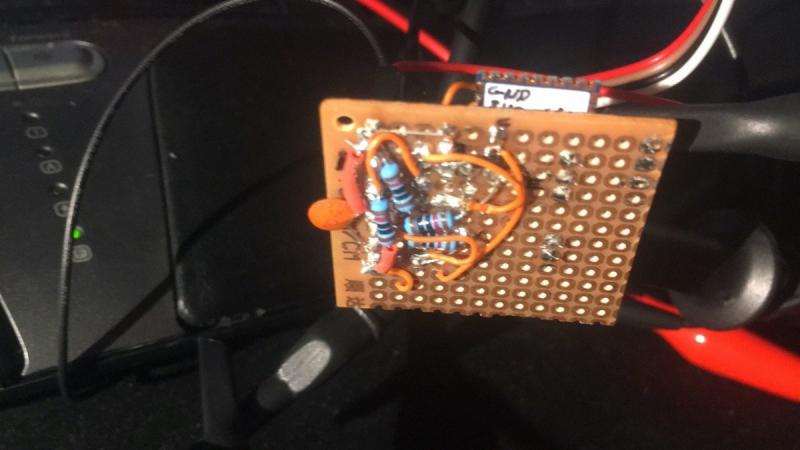 The stock firmware that runs on this thing occupies the MISO pin with a blinking LED (indicating states "pairable" and (dis)connected). It turns to solid when it pairs/connects (yellow channel on my oscilloscope): 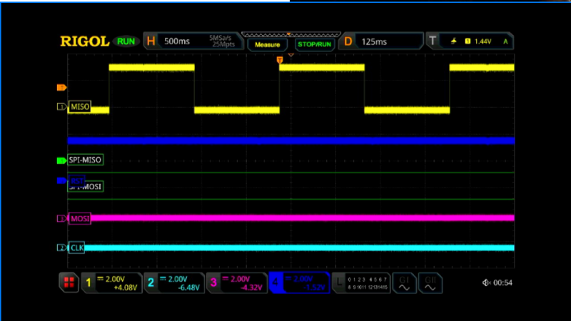 The 194-page ARM968E-S technical manual that Mitxela alludes to is fairly straightforward to find over arm.com: https://static.docs.arm.com/ddi0311/d/DDI0311.pdf. I was toying with the idea to interface with SPI and dump the flash section (from 0x000000 to 0x0003FFFF) by using SPI commands as indicated in the datasheet: 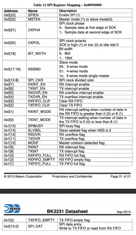 But then I encountered the MISO hiccup above... the QFN32 version does not have any JTAG pins so I thought that SPI would be the only way to go to overwrite the FLASH section... then after reading the MFC section on the datasheet, I realised that there are relatively specific instructions for reading, erasing and flashing by using the PPROG pin: 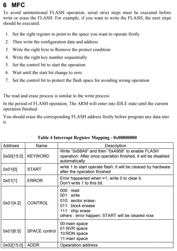 There are plenty of bluetooth toys with this IC in them: https://www.amazon.com/Bluetooth-Controller-DESTEK-Cardboard-Separate/dp/B0132TQADQ So I reckon it would be a nice, relatively easy to port (because ARM) and cheap target for very low cost designs. I have been trying to send HID Bluetooth reports to emulate a mouse by sending codes via the UART->Bluetooth, but I'm not sure the stock firmware is up to the task, unfortunately :/ 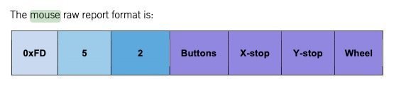 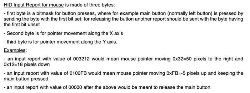 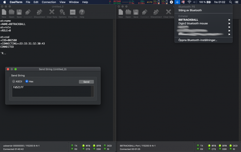 Last edit by brainstorm at 18 Jul 2020, 03:53 AM ------------- |
| [top] | |
| brainstorm | Posted: 16 Jul 2020, 03:16 PM |
|
@braincode Member Posts: 9 Joined: 16-July 20 |
For the record, I seriously doubt that this thing can do anything useful other than a plain serial BT-UART bridge with the "Bolutek" stock firmware it usually ships with. See the attributes for a commercial bluetooth mouse (Digio2, not necessarily Beken3132 based, I have not opened it), versus the "BBTRACKBALL", which is the BEKEN module with CoD (class of device) of a mouse defined via AT command AT+COD002580 and re-plugging the module. 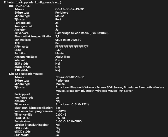  If somebody can post similar screenshots connecting the RN42 (or re-flashed HC-05) over here, it would greatly satisfy my curiosity on this topic ;) Here's an example Arduino code one could use to setup this quickly: https://github.com/Marchanjo/SimpleMouseBT_RN42 (NOTE: does not work with the BK3231, different beast and AT commands). PS: Sorry for the bluetooth attributes being in Swedish, I hope I get my point across anyway ;P Last edit by brainstorm at 16 Jul 2020, 03:25 PM ------------- |
| [top] | |
Sign in to post a reply.