
| ATIoNo | Posted: 11 Jul 2020, 10:37 PM |
|---|---|
 Member Posts: 4 Joined: 30-June 20 |
During initial assembly of the clock kit I investigated display issues, I affixed the right hand display driver upside down. I started removing it without proper equipment and damaged things and stopped. After getting some better rework equipment I put down a replacement display driver as the original was damaged beyond reuse. The issue as it stands is that the top and top leftmost segment in the 4 digit second cluster are not illuminated. It's difficult to get my mobile phone camera to focus at the lengths the details for these pictures is required. I've repaired a broken trace or two but I couldn't find any documentation on the pinout for the missing segments. I was hoping it'll be fixable with some miracle trace repair but if not I suppose I'll have to infer the second count. Ignore the nail clippers they had some tweezers in there. 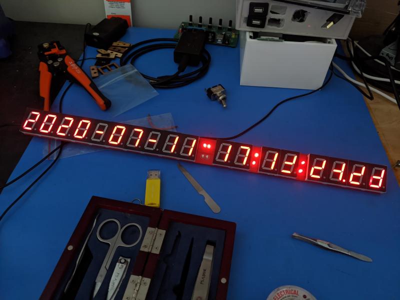 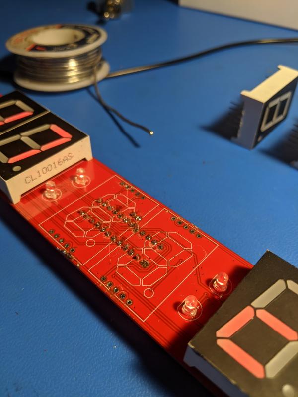 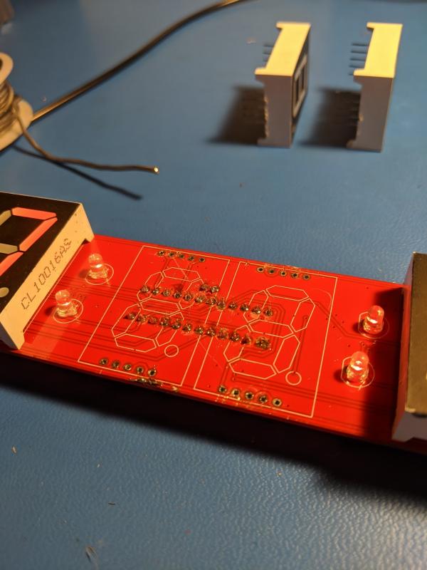 Is there any chance those segments being out are caused by a damaged trace? How are these character displays pinned? The replacement display driver is a MAX7219CNG+ but has a 4 digit code 2016 as opposed to 1904 on the original chip. Last edit by ATIoNo at 11 Jul 2020, 10:45 PM ------------- |
| [top] | |
| mit | Posted: 12 Jul 2020, 11:04 AM |
 yeah whatever Admin Posts: 687 Joined: 4-May 16 |
Hi, the new MAX7219 chip should work fine, I don't think a different date code should make much difference. At worst, it might drive them at a slightly different brightness. The top and top left segments are labelled A and F. Both of these traces go up from the chip and along the top of the board, here's some screenshots with the traces highlighted: 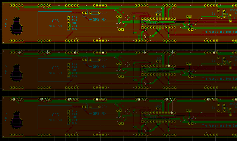 This is looking at the back of the clock. 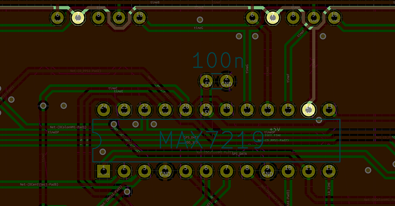 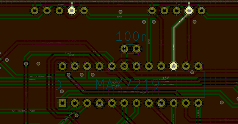 Might also help to show these two bits from the datasheet for the driver chip: 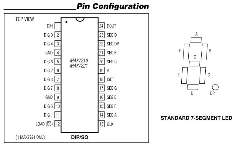 I think it's possible it's a damaged trace, it might also be a dodgy solder joint. I would recommend cleaning the solder joints with flux cleaner if you can. It gets rid of all the brown smudges and makes it much easier to spot problems. Isopropyl alcohol should work if you don't have the proper stuff. I would start by checking the continuity of the traces you think might be damaged, if you have a multimeter with continuity tester you can just touch the pins of the digits and the pins of the MAX chip and see if there's a good connection. ------------- |
| [top] | |
| ATIoNo | Posted: 13 Jul 2020, 04:40 PM |
|
Member Posts: 4 Joined: 30-June 20 |
Segment f is fixed, it must've been a bad joint, I went over them all. Once I find my multimeter I'll tone the traces and see if I can fix segment A. Thanks a million for the reply, you've helped greatly. ------------- |
| [top] | |
| ATIoNo | Posted: 28 Jul 2020, 10:38 PM |
|
Member Posts: 4 Joined: 30-June 20 |
It took a few hours with the proper tools but all my segments are now lit. I couldn't have done it without those trace images you posted. Thank you again. ------------- |
| [top] | |
| mit | Posted: 29 Jul 2020, 01:57 PM |
|
yeah whatever Admin Posts: 687 Joined: 4-May 16 |
Excellent, thanks for the update. ------------- |
| [top] | |
Sign in to post a reply.