
« PreviousPages: 1 [2]
| mit | Posted: 10 Mar 2023, 05:43 PM |
|---|---|
 yeah whatever Admin Posts: 687 Joined: 4-May 16 |
QUOTE
I assume you didn't mean the display chip (the MAX7219) - if the clock was still displaying with the display chip removed we would have discovered something new to science.Removing both the transistors, and then the display chip With both transistors removed, the time side shouldn't be displaying anything at all. Would you say it's dimmer than before, or about the same brightness? With the 50K resistor removed, what's the resistance between ISET_DATE and +5V ? Sorry it's taking me so long to figure out the problem, I feel like we've nearly got it. It'll all be worth it when it's working perfectly. ------------- |
| [top] | |
| Paradox | Posted: 10 Mar 2023, 07:55 PM |
 Member Posts: 16 Joined: 2-March 23 |
Yeah haha I mean the 7 segment displays. I haven't desoldered any of the ICs. Its a little bit dimmer; in a bright room its rather dim, but in a dark room its plainly visible. The resistance between the ISET_DATE pin on the driver IC and the +5V pin on the plug socket (unplugged and disconnected) is around 210 kΩ And no worries! Debugging isn't ever easy. Part of why its a project, this is part of the experience Last edit by Paradox at 11 Mar 2023, 06:42 AM ------------- |
| [top] | |
| mit | Posted: 11 Mar 2023, 11:22 AM |
|
yeah whatever Admin Posts: 687 Joined: 4-May 16 |
Around 210k, that's with the 50K resistor removed? It's clear evidence of either a short, or that the chip is damaged. The ISET_DATE track in its entirety just goes from the 50K to the pin on the display driver: 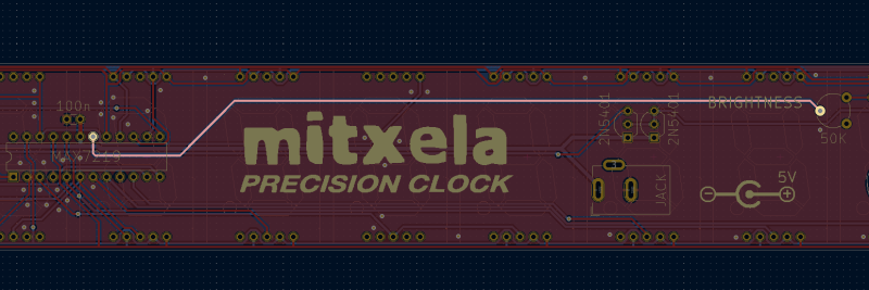 I would examine closely for any damage on that track, and again look carefully at the legs of the MAX7219 chip. And if you can't see anything, it might be time to remove the MAX7219 and look underneath it. Perhaps there is a solder bridge or flux residue on the underside. At least if you remove it, you could then check the resistance again between that track (now with nothing connected to it) and +5V. Should be infinity. Take some close up pictures of the board under the chip if you do remove it. ------------- |
| [top] | |
| Paradox | Posted: 13 Mar 2023, 08:48 PM |
|
Member Posts: 16 Joined: 2-March 23 |
Yes, that was with the 50kΩ removed. Removing the MAX7219 IC and testing only that trace shows virtually no resistance (>0.1Ω). The trace visually looks fine, no obvious fractures or breaks. Measuring between the trace and +5V does have infinite resistance. Here's a close up from the board immediately under the MAX7219 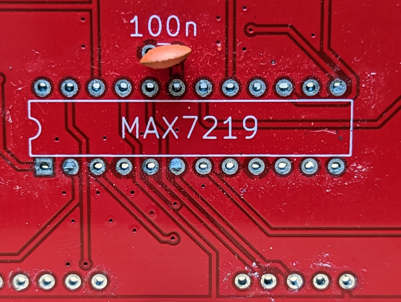 ------------- |
| [top] | |
| mit | Posted: 14 Mar 2023, 06:18 PM |
|
yeah whatever Admin Posts: 687 Joined: 4-May 16 |
OK. Can you measure the resistance between the relevant pins on the IC you've now removed? It would be pins 18 and 19. If necessary I can post a couple more MAX7219 chips to you. ------------- |
| [top] | |
| Paradox | Posted: 14 Mar 2023, 09:43 PM |
|
Member Posts: 16 Joined: 2-March 23 |
Resistance between pins 18 and 19 started at .4MΩ and slowly rose to just over 1MΩ ------------- |
| [top] | |
| mit | Posted: 14 Mar 2023, 10:27 PM |
|
yeah whatever Admin Posts: 687 Joined: 4-May 16 |
In that case, I would try plugging the chip back into the clock. You don't necessarily need to solder it in, just pushing the legs into the holes should be enough to see if it's behaving any differently (though maybe not all the segments will light up). Turn it on (without fitting the 50K or the transistors again) and see if the remaining digits on the date side are still at full brightness. It's possible the act of un-soldering it has resolved the short. ------------- |
| [top] | |
| Paradox | Posted: 15 Mar 2023, 06:28 AM |
|
Member Posts: 16 Joined: 2-March 23 |
The date digits started out barely visible, but after about 10 seconds of being powered on, illuminated to full brightness. After about 30 seconds, they flickered a few times, went out, then returned to full brightness again. 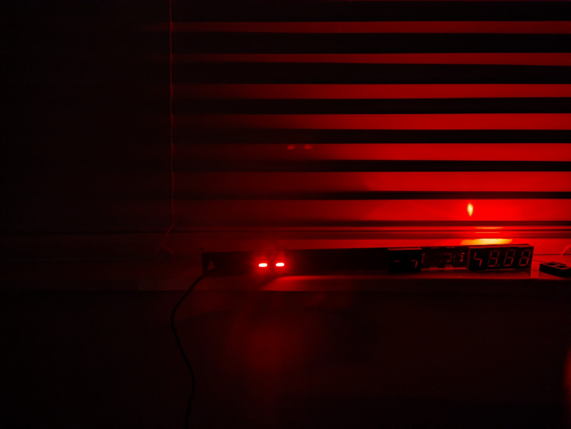 ------------- |
| [top] | |
| mit | Posted: 15 Mar 2023, 12:23 PM |
|
yeah whatever Admin Posts: 687 Joined: 4-May 16 |
I'm not sure what to make of that. With nothing connected to ISET it shouldn't be able to display anything (and neither should the time side). I can post a couple more of the maxim chips to you and we'll see if they behave any differently. ------------- |
| [top] | |
| Paradox | Posted: 15 Mar 2023, 10:00 PM |
|
Member Posts: 16 Joined: 2-March 23 |
For what its worth, removing the date maxim chip causes the date side to go completely dark, as expected. Time side is still very faintly illuminated, going through its count-up. ------------- |
| [top] | |
| mit | Posted: 20 Mar 2023, 05:20 PM |
|
yeah whatever Admin Posts: 687 Joined: 4-May 16 |
I posted a couple of replacements to you. While we wait for them to arrive it's worth looking further into the date side I think. On a normal working clock, if you remove the maxim chip from the date side, the time side goes completely blank. In fact, if the chip isn't fitted, the time side won't work at all - putting the date side chip back will leave the display blank until the clock has been power cycled. Both chips I originally sent were fully tested, I figured maybe one of them got damaged during soldering or something, but it's unlikely both of them are damaged. It might be worth removing the remaining maxim chip, checking for shorts there, and then maybe swapping the two chips over and seeing what happens. If you do get to a state where the display is fully blank when powered on (but GPS still lights up), you could then try adding a 20K resistor from each ISET pin to +5V, to see if you can get the display into a working state bypassing the brightness circuit. ------------- |
| [top] | |
| Paradox | Posted: 15 Jul 2023, 06:24 PM |
|
Member Posts: 16 Joined: 2-March 23 |
Sorry for the very long delay, life got busy and I had to put the project on the shelf for a while. I got the new driver chips installed, and the clock seems to be working flawlessly. Running it off a USB Battery pack, I can take it from light to dark, with clean transitions between. I still need to sand and glue the indicator black outs, but that's a more mechanical process, and shouldn't be a problem. Thank you very much ------------- |
| [top] | |
| mit | Posted: 16 Jul 2023, 11:29 AM |
|
yeah whatever Admin Posts: 687 Joined: 4-May 16 |
Fantastic, thanks for the update! ------------- |
| [top] | |
« PreviousPages: 1 [2]
Sign in to post a reply.