
| teevee | Posted: 27 Dec 2017, 07:11 AM |
|---|---|
 Member Posts: 3 Joined: 27-December 17 |
Hi, Are there any updates concerning the breath controller project? :) I would like to have one myself for my Yamaha VL70m Links: https://mitxela.com/projects/breath_controller_mk_ii https://mitxela.com/projects/breath_controller ------------- |
| [top] | |
| mit | Posted: 27 Dec 2017, 02:08 PM |
 yeah whatever Admin Posts: 687 Joined: 4-May 16 |
Hi there (are you the guy with the yamaha VL70M who emailed me a couple of months ago? if so, sorry I didn't get back to you!) No real progress unfortunately. I've had a lot of people asking to buy breath controllers like I showed in the video, I just need to update the design a bit so that I can assemble a batch of them. The annoying bit is that piezo pressure sensor is pretty expensive, something like £15 each so I'm hesitant to buy a whole load of them just yet. The ideal design would be something with both a voltage-controlled-attenuator, like in the breath controller mk II, and also a USB/MIDI output, because that's relatively easy to add, and the USB can also be the power source. When I have time, I'll try and put something together, maybe I can sell it as a kit. I also had another idea somewhat related, which was to make a MIDI controller in the form-factor of a tin whistle. This would mostly be just for fun, but I could combine the breath controller and a bunch of LDRs to detect which holes are being covered, and fit the whole thing inside of a real tin whistle. But I've been so busy lately, this one might have to wait. ------------- |
| [top] | |
| teevee | Posted: 27 Dec 2017, 05:56 PM |
|
Member Posts: 3 Joined: 27-December 17 |
Hi, yeah, I’m that guy with the Yamaha VL70m and no problem, I fully understand the concept of time priority. The whole topic just came to my mind as I was scrolling on the local page for used gear and I saw a Yamaha BC-3 for 450 € and a Yamaha BC-1 for 100 € used. As you mentioned above, the interest is there but the current options out there is not thought-out or are overpriced, which is a shame because the concept really got some potential for giving music more expression. I don’t know what the core-cost would with a proper design, but have you thought about a crowdfunding project (like kickstarter?) and then the interested end-users could help finance it, if money is the problem :) (I don’t think that getting the interest on the project is the problem here) ------------- |
| [top] | |
| mit | Posted: 28 Dec 2017, 10:47 PM |
|
yeah whatever Admin Posts: 687 Joined: 4-May 16 |
It's tempting - but sadly, at the moment, time is more of a problem than anything else. ------------- |
| [top] | |
| wolfpaw98 | Posted: 1 Mar 2018, 06:07 PM |
 Member Posts: 1 Joined: 1-March 18 |
Thanks for posting this project! I am very intrigued and would like to build one myself. Although I have built some electronics projects before, my knowledge of circuit design is limited. I thought that it might be useful to combine the two breath controller components into one and I have attempted to do this in the schematic attached. I do have some questions about the circuit which I was hoping you could answer before I start to build my own. 1. Could you take a look at my circuit and let me know if there are any errors? EDIT - I just noticed that a 5V trace is missing from the Vcc pin on the MAX4389 to the 5V on the pressure sensor. 2. What type of LDR did you use? There are several types and I just want to make sure that I buy the correct one. 3. In your schematic, all three caps are identified as 10 uF, yet in the photos of your build, the cap that bridges the power in looks physically smaller than the ones used in the audio lines. Can you confirm that the power cap is 10uF? 4. Is the trimpot that is used to adjust the voltage to the LED a 2K ohm and is there also 1K ohm resister in line as shown? 5. Is the trimpot used to adjust the voltage to the MPXV4006 a 10K ohm? 6. How did you set the opamp gain to 20? Which of the 22K resistors (I'm assuming the lower one) did you change and to what value? 7. What value trimpot did you use to attenuate the pressure sensor's signal (I'm assuming the top 22K resistor was replaced) and how does it connect in the schematic (I'm assuming it's just a two wire connection)? Is it as simple as replacing the 22K resistor with a 20K trimpot? Thanks in advance for answering these questions. I would love to build one of these and eventually figure out how to incorporate a MIDI output so that it could be plugged into any synth! I also think that an enclosure for the LED/LDRs could be designed and 3D printed. I would be happy to take this on. 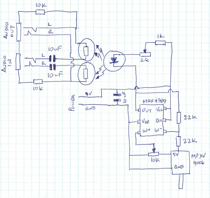 Last edit by wolfpaw98 at 1 Mar 2018, 10:51 PM ------------- |
| [top] | |
| mit | Posted: 3 Mar 2018, 02:51 PM |
|
yeah whatever Admin Posts: 687 Joined: 4-May 16 |
Hi wolfpaw98. Most of the component values are chosen quite arbitrarily, I wrote down what the final values were but for most of these prototype things I try lots of different values until it works. For the capacitors, it might be that I used one with a different voltage rating, I can't remember. I would say it's a good idea to have the two audio decoupling ones be identical. Most audiophiles would feel disgust at using electrolytic caps for this, but I've not noticed any problems. I think something like a polypropylene film capacitor would be more appropriate. The capacitor across the power probably isn't important, it might even be better to replace this with a small ceramic cap. The LDRs were a pack of ten from ebay. I measured their resistance to range from about 10k to a few megaohm, which is why I chose the 10k resistors to go with them to form potential dividers. I'd say just try building it, maybe just the left hand side of the circuit, and see if it works by manually lighting up and dimming the LED. The trimpot for the LED was found by trial and error, I would really recommend building a test circuit and seeing what it needs. In fact if you only have one LED, you probably don't need a trimpot, especially if you're going to have controls on the op-amp for offset and gain. Gain on an op-amp is easy, if it's wired up with negative feedback (as is nearly always the case). It's the ratio between the two resistors. So the values don't really matter as long as one of them is 20x bigger than the other. There are loads of tutorials on op-amp circuits on the web, search for inverting amplifier. To attenuate the signal from the sensor, you use all three terminals of a trimpot, one to ground, one to the sensor, and the wiper terminal is then your attenuated output. Potentiometers are easy if you think of them as selecting a signal that's a certain percentage of the two end terminals: turn it one way, and the wiper will be connected directly to the input signal, turn it the other and it will be connected directly to ground. In between it smoothly selects a blend of the two voltages. OK, I'm looking at your diagram and it does seem to have a mistake, the trimpot at the bottom right is not wired up correctly. The 5v of the sensor should be connected straight to the 5v power supply. The trimpot's terminals should be 5v, ground, and in+ of the opamp. I would recommend staying away from the max4389, I did buy that one by mistake! There are plenty of other rail-to-rail opamps, many in bigger packages that aren't quite as bad to solder to. Even a soic-8 package would be easy in comparison. In fact if you're not worried about the yamaha protocol, you could simplify the circuit a lot. Maybe you don't even need the op-amp at all. On the other hand, having the gain adjustment is very useful. ------------- |
| [top] | |
| ijfritz | Posted: 8 Mar 2018, 07:00 PM |
 Member Posts: 1 Joined: 8-March 18 |
Hello -- I started experimenting with breath control and wind synthesis in the early 1970s. Good to finally see some other activity in this area. Brief writeups are on on my website. The breath sensor circuit given is an early simple version. The final circuit includes diode-switched attack rate, proportional plus derivative response and a retriggering detector. Ian Fritz http://ijfritz.byethost4.com/SoS/sos_over.htm ------------- |
| [top] | |
| mit | Posted: 8 Mar 2018, 09:35 PM |
|
yeah whatever Admin Posts: 687 Joined: 4-May 16 |
Neat! Looks far more refined than my efforts. Is there a demo of what it sounds like anywhere? Or a video? I'm particularly interested in your approach to the pitch bending. I can't quite see how the control works, do you press on the string with your thumb, or slide it to the side? And, more importantly, does it feel natural to play bends using it? For the pitchbend device I built for Brendan Power we used a tiny joystick, which worked reasonably well, but I still feel like there's a better mechanism possible. My main wind instrument is (or was) the saxophone, so I've wondered about the feasibility of measuring jaw/bite pressure and feeding that into the bend amount. Have you tried this, or do you route the bite pressure to some other control? Using a derivative response is a really interesting idea. One of the parts that feels unnatural in my breath controller is that there's no momentum to it, the output is just directly proportional to the input pressure. I'm really curious as to how effective your circuit is. Thanks for sharing. ------------- |
| [top] | |
| teevee | Posted: 16 Mar 2018, 11:26 AM |
|
Member Posts: 3 Joined: 27-December 17 |
QUOTE (ijfritz)
Hello -- Hi Ian, I checked your webpage. I love this steampunk look, very inspiring and good job! I totally agree with you, breath controllers are really an underrated topic and especially for hardware. I find that very strange due to that many end-users has focus on expressive performance (example Touché and Roli seaboard) I would love to see someone actually taking the concept of breath controllers and making a full affordable potential out of it. < Taking it to the next level. ------------- |
| [top] | |
| middlec | Posted: 20 Aug 2018, 07:24 AM |
 Member Posts: 1 Joined: 20-August 18 |
I'd like to sponsor you with parts, for a percentage of what is made. Or if you are into it I'd pay for mass production and profit share with you. Thank you for posting the information freely online. I realize that I could use the info to get these made. I'd prefer if you were involved in profit - let me know in what way that could work for you. ------------- |
| [top] | |
| Barweiss | Posted: 2 Mar 2019, 02:26 AM |
 Member Posts: 1 Joined: 2-March 19 |
Hi all. I am new here, and found you via a youtube on breath controllers and melodica. I love playing the melodica AND playing synths with breath control. I would be a paying customer for a usb midi output device, if and when! If there is a list, you can put me on it. ------------- |
| [top] | |
| Magicaldog | Posted: 15 Aug 2020, 11:25 PM |
 Member Posts: 1 Joined: 15-August 20 |
Although this thread looks dead I am extremely interested in building this: https://mitxela.com/projects/breath_controller Is the schematics on the above page relevant for getting it to work as expected ( Yamaha BC3 or better ? ) But I am not an electronic expert by a long shot and have some questions that I hope someone can answers before I Are these all the required components: 1 X Freescale MPXV4006DP 1 X MAX4389 Opamp 2 X 22K Resistors 2 X Trimpots / Cheers ------------- |
| [top] | |
| mit | Posted: 16 Aug 2020, 10:28 AM |
|
yeah whatever Admin Posts: 687 Joined: 4-May 16 |
QUOTE (Magicaldog)
That is mostly correct but avoid the opamp, there are many rail-to-rail opamps that come in a DIP package.Although this thread looks dead I am extremely interested in building this: If you want it to work with original yamaha keyboards you will also need to worry about voltage. I modified my keyboard to run on 5V instead of 9V. You may need to add a regulator for the Freescale part. ------------- |
| [top] | |
| Pablo | Posted: 9 Apr 2021, 05:00 PM |
 Member Posts: 2 Joined: 9-April 21 |
Hello! I've built the breath controller, and I had a very good result. However I couldn't find the max opamp in my country so it's not very sensitive. Question: is there any replacement for it that is easier to find? I'm supplying 5v to the breath controller. I'm just an enthusiast and comparing datasheets is beyond my knowledge. Thank you very much for your answer and for sharing your projects! Pablo ------------- |
| [top] | |
| mit | Posted: 11 Apr 2021, 12:20 PM |
|
yeah whatever Admin Posts: 687 Joined: 4-May 16 |
Any rail-to-rail op-amp should do, it doesn't need any fancy features. MCP602 is a 5V rail-to-rail op-amp available in a DIP package that should work. ------------- |
| [top] | |
Sign in to post a reply.