
| rodrigomx | Posted: 8 Jun 2017, 10:07 PM |
|---|---|
 Member Posts: 3 Joined: 8-June 17 |
Hi, I Success have a RN42 Firmware on HC-05 module, if I search on my android device i see Joystick Icon and the name i set with RN42 Commands. However, im stuck with the "Virtual test", i use FTDI USB Serial Module to Flash and comunicate with the chip (i use Monitor Serie Arduino), but how i send 0xFD values? what programing language i have to use for the ATtiny2313 (tn2313adef.inc) ? Thank you for a great tutorial. Chears ------------- |
| [top] | |
| mit | Posted: 8 Jun 2017, 10:34 PM |
 yeah whatever Admin Posts: 687 Joined: 4-May 16 |
You don't need the ATtiny2313, you can use the Arduino directly. I've never used an Arduino but I think it would look something like this: byte report[8]= { 0xFD, 0x06, 0x00, 0x00, 0x00, 0x00, 0x55, 0xAA }; Serial.write(report, sizeof(report)); ------------- |
| [top] | |
| lepond | Posted: 12 Jun 2017, 02:18 PM |
 Member Posts: 7 Joined: 8-June 17 |
QUOTE (rodrigomx)
Hi, It doesn't need to be the ATtiny2313. There's a library for Arduino that you can use to make everything easier. Basel's BPLib: https://github.com/baselsw/BPLib This library is made to work with Arduino Mega and other boards that have Serial1 available. For Arduino Uno, Nano, Micro, etc, you have to edit the library just a bit to make it work. Or, you can download an already modified library by Conor O'Neill. He already modified to work with UNO, and made little tweaks, like adding commands to volume up, volume down, etc. Conor's BPLib: https://github.com/conoro/bandon-bluetooth-button Then you'll be able to send commands like this QUOTE
BPMod.volumeDown(); ------------- |
| [top] | |
| rodrigomx | Posted: 13 Jun 2017, 10:58 PM |
|
Member Posts: 3 Joined: 8-June 17 |
QUOTE (mit)
You don't need the ATtiny2313, you can use the Arduino directly. QUOTE (lepond)
Thank you, this is helpful, the arduino is just for test and i success made the test, now i like to know how compile tn2313adef.inc, main, etc. Well, this need more context. I have a custom Joystick Sanwa Arcade (6 buttons + 1 start + 1 coin + 2 hoykeys, 10 buttons total), i use batocera linux wich is full compatible with bluetooth, i have the tv too away from armchair and usb extensions is not a option so... I already have HC-05 (Custom firmware RN42), ATTINY2313 and miniPro, my question is how get .bin for miniPro 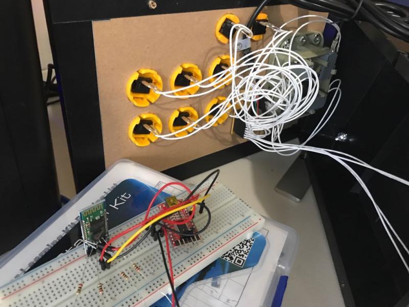 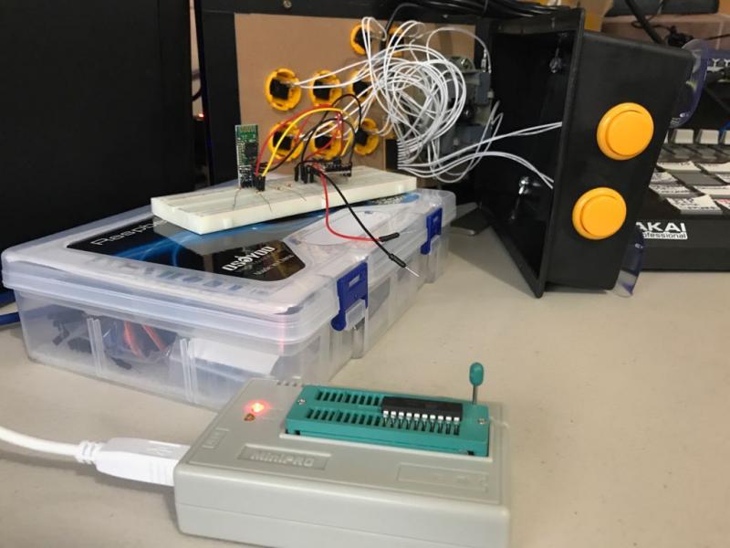  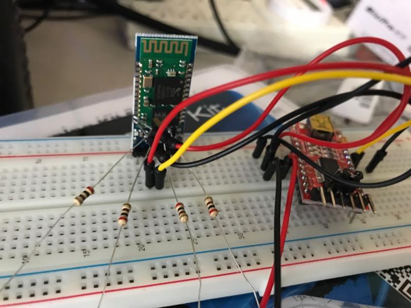 ------------- |
| [top] | |
| mit | Posted: 13 Jun 2017, 11:57 PM |
|
yeah whatever Admin Posts: 687 Joined: 4-May 16 |
Fair enough, if you want to use the exact code I wrote for the attiny2313, you need to assemble it. If you are using windows you can install AVR studio, select "new 8-bit assembler project", paste in the code and hit build. Alternatively you can try out gavrasm which might be easier. For the UART baud rate to match, you will need to set the correct fuses on the ATtiny2313, because from the factory it will have the DIV8 bit set. I think the right command would be: QUOTE
avrdude -U lfuse:w:0xe4:m But, you don't have to use AVR assembly to program an ATtiny2313. I know that some people have ported the Arduino core to it, so it can be programmed with the Arduino IDE. Take a look here: https://playground.arduino.cc/Main/ArduinoOnOtherAtmelChips ------------- |
| [top] | |
| wongman44 | Posted: 31 Jul 2017, 09:33 PM |
 Member Posts: 1 Joined: 31-July 17 |
Hi Mit First of all, your tutorial is awesome. i thought, this i want to try to make my self. I'm very new and noob at forums and diy things, so lots of things and terms i having difficulty to understand. So i do my best what kind of problems i having on my project. i tried to follow the steps in your tutorial, but it didn't work for me. I have bought the FTDI usb serial com module. bluesuite giving me no spi error. So i went searching online for other tutorials. And found one from Evan Kale with the parallel port. That i manage to flash the rn42 to my hc05 bluetooth module. My idea is flash the hc05 with the rn42 firmware and a have merge the hc05 bluetooth address back to the hc05 with the new firmware. i'm planning to connect the hc05 to my teensy 2.0 to connect my diy game pad controller. i'm using the teensy 2.0 as a controller. use arduino ide to load my sketch with the mapping to which button to which pin. My situation what i have done so far. I have flashed the rn42 to my hc05 and now try to configure my hc05 with a arduino nano. uploaded the sketch but my serial monitor did not work. when i try to send a command, i get no response. So i tried the FTDI method in your tutorial. But could not follow the steps how to configure the hc05 with a FTDI usb serial com module. So i'm lost here. do not know what to do. i did the wiring, my led light lids up on my hc05. but it's not flashing. So my hc05 is not entering to command mode. And also my hc05 breakout board does not have the "key" pin and mine have a "EN" pin. I do not know what the difference are on both hc05. i hope i can get some directions or help how i get to get this working? ------------- |
| [top] | |
| mit | Posted: 3 Aug 2017, 08:40 PM |
|
yeah whatever Admin Posts: 687 Joined: 4-May 16 |
Hi, if you have flashed it correctly then you just need to get the serial monitor working. It's probably at the wrong baud rate, is there an option to change the baud rate in the arduino serial monitor? Or if you use the FTDI cable, you can use any software you like as a terminal. I like "bray's terminal" and also "PuTTY", but there are others too. Just make sure you set the baud rate to 115200bps, and the other settings should be their defaults (8 data bits, 1 stop bit, no parity). ------------- |
| [top] | |
| rodrigomx | Posted: 19 Aug 2017, 10:17 PM |
|
Member Posts: 3 Joined: 8-June 17 |
Hi, just to let you know i finally made my arcade bluetooth gamepad, i end it with arduino mino pro, RN42 (HC-05) configuration just like you said and loop to read the state of the buttons. Thank you.
Full code: https://github.com/RelaxMX/Arduino-Bluetooth-GamePad/blob/master/Joy.ino 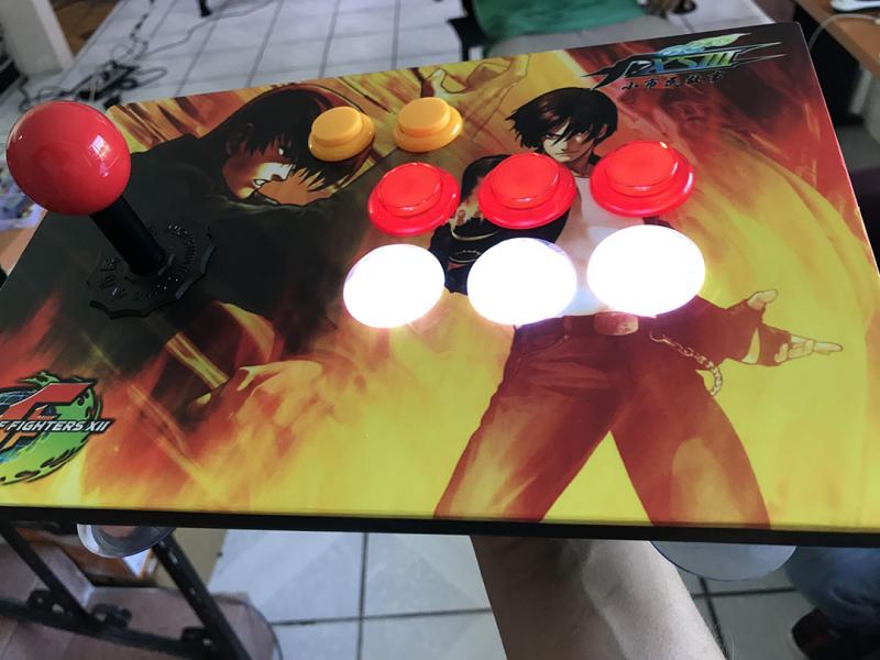 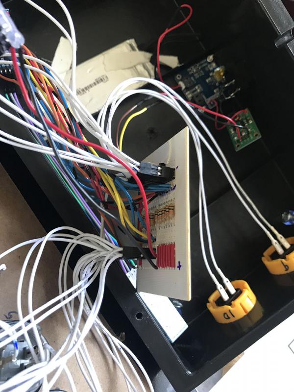  ------------- |
| [top] | |
| mit | Posted: 20 Aug 2017, 11:03 PM |
|
yeah whatever Admin Posts: 687 Joined: 4-May 16 |
Looks great - thanks for sharing! ------------- |
| [top] | |
| ChesLans | Posted: 7 May 2018, 04:56 PM |
 Member Posts: 1 Joined: 7-May 18 |
spam (well obfuscated spam, but definitely spam) Last edit by mit at 23 Jun 2019, 01:09 AM ------------- |
| [top] | |
| thepolish | Posted: 24 May 2018, 01:36 AM |
 Member Posts: 5 Joined: 24-May 18 |
So I took the complete opposite approach of soldering wires on to the hc05 and put the clothes pin idea on steroids. I picked up some .68mm pogo pins and went to work with blender and then tinkercad - and 3d printed this wonderful contraption to program the chip and limit soldering so I could make a few of these. The goal is of course to have 2x SNES, 2x Mega Drive, 2x NES and 2x of whatever the heck else I can find to put my hands on. The first design was close, I tweaked and printed it and wouldn't you know it works well enough. so next I decided to work on it some more and am currently printing a desktop jig which I can swap in and out HC05/6 boards in with ease. Solder the ends of the wire to the pogo pins - feed the wires, and hook up to the programmer. Thank you for all you've done - not only have I learned a little bit of AVR Assembly Language with this project, but I've actually created my first functioning model because of it. I have a little more tinkering to do with the hc05 but all in all. _________________________ _________________________ First Design 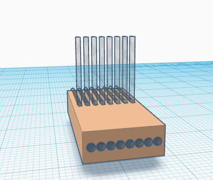 Final Design 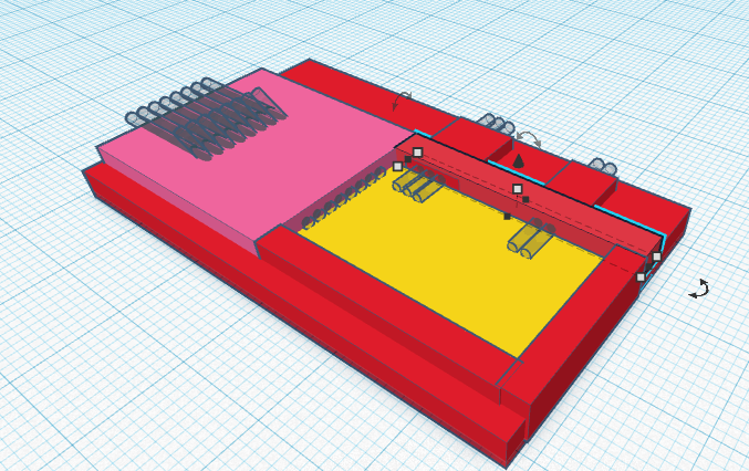 3d Print Render 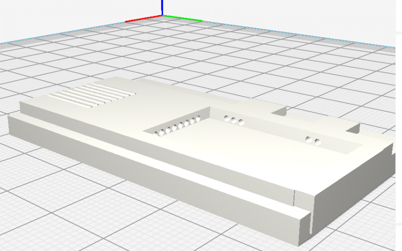 With Pins 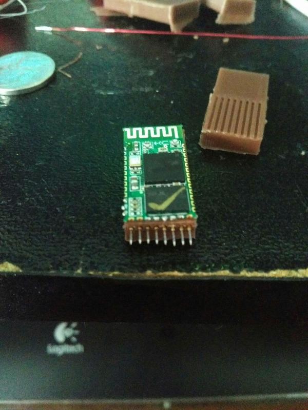 How Wire Will Be Fed 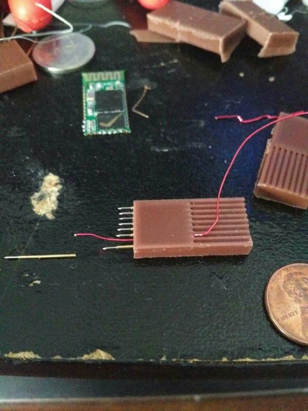 _________________________ _________________________ I'm pretty happy. I have one working Mega Drive pad working as of right now with android but not fully as windows 8 hates this thing as a joystick. I'm curious - in AVR - why did you use 0240 rather than 0210 for gamepad as this only has a D Pad rather than a joystick? I know nothing of AVR but am trying to learn this language (well, all I really know right now is a little bit of VBS for Excel) so I can play more wit this stuff. For now though I'm using yours straight up as this code does pretty much all I need - just couldn't figure out why the profile selection? (side note - photos sometimes load sometimes don't when I viewed my post - I had 5 of them in there). Thanks again! Last edit by thepolish at 24 May 2018, 01:41 AM ------------- |
| [top] | |
| mit | Posted: 24 May 2018, 05:24 PM |
|
yeah whatever Admin Posts: 687 Joined: 4-May 16 |
Hi, nice jig you're building there. It looks like you've 3D printed the bits end-on, interesting. I can't remember why I went for 0240, it might have been because I wanted to use it with a certain emulator that wanted that format, I'm not sure. You could use either profile I guess, just be sure to have the reports sent in the right format. ------------- |
| [top] | |
| thepolish | Posted: 25 May 2018, 12:39 AM |
|
Member Posts: 5 Joined: 24-May 18 |
Wonderful. Jig came out very well. I will try 210 because why not. Also, cut the hc05 antenna trace at 1mm and thew a 29.5 mm copper wire on it from where the feed comes out of the cap. Range does indeed improve greatly, infact so much so that windows now doesn't hate this device. Retroarch does though, so maybe 210 will help.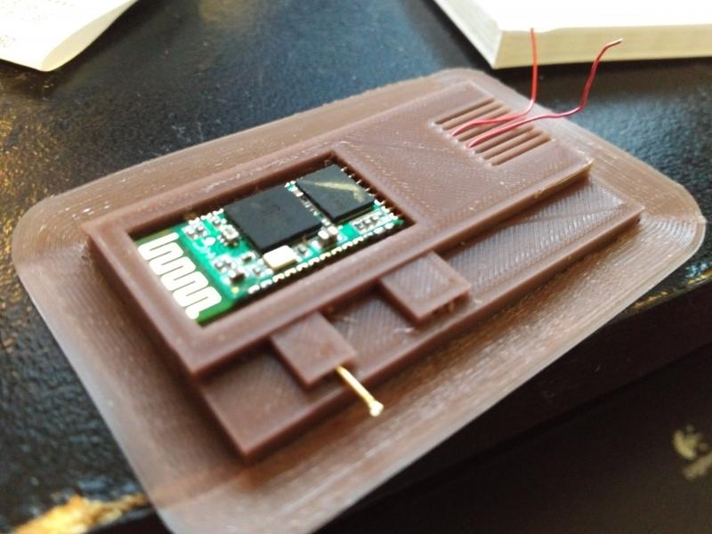 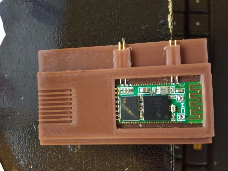 Last edit by thepolish at 25 May 2018, 01:58 AM ------------- |
| [top] | |
| mit | Posted: 25 May 2018, 09:30 AM |
|
yeah whatever Admin Posts: 687 Joined: 4-May 16 |
That's really cool. I hadn't considered changing the antenna, what made you choose 29.5mm ? I guess the wavelength of light at 2.4GHz is 12.5cm, so quarter-wavelength would be 31.25mm. But then I suppose the speed of light in copper is different. Google says the velocity factor for open copper varies, some websites say 93% which would fit the numbers here. Well I recently discovered you can get a really cheap 2.4GHz spectrum analyzer called RFexplorer. It's still ~$150 but spectrum analyzers normally cost thousands. With that, you could maybe check the performance of your antenna, and calculate a new "trim offset" value to go into that PSKey. There is also a cheap vector analyzer called the N1201SA that could potentially measure the performance of your new antenna. ------------- |
| [top] | |
| thepolish | Posted: 25 May 2018, 10:33 AM |
|
Member Posts: 5 Joined: 24-May 18 |
Using that roughly 31mm as the 1/4 wavelength I cut the trace as close to 1 mm with an razor as I could, then cut the wire using calipers to measure both. I figured that would be the best way to get close. Aside from that the 31.25 should be center frequency of the 2.4 band, so though important, I figured a hair off wouldn't make or break it. I'm curious if any of the local radio guys here might have an analyser that might be able to to do the same. I'll ask this morning on my way into work. ------------- |
| [top] | |
Sign in to post a reply.