
| VonBarth | Posted: 24 Apr 2019, 06:38 PM |
|---|---|
 -]Dream Machine[- Member Posts: 7 Joined: 30-March 19 |
Well mit, I have a LOT more appreciation for your solder job now after trying it myself (fail :P) it's the smallest solder job i've ever tried, and I was confident I could do it, but there was one thing I wasn't counting on and that was the brass pieces coming right off!! The first two solders I made came out OK I guess, but the second two I managed to break the brass right off. I figured no sweat, Ill just flip it over and use the brass on the other side, but the same thing happened!! heheh. I think once you lose one side the probability of losing the other side increases. Anyway i'll probably order another one and try again. I think i'll try soldering the wire on the side instead of the end this time if you know what I mean. p.s. after I flipped it over, I turned my iron down to 250 (from 300) but that didn't seem to help. ------------- |
| [top] | |
| mit | Posted: 29 Apr 2019, 12:10 PM |
 yeah whatever Admin Posts: 687 Joined: 4-May 16 |
Ah, it's annoying when that happens. It's sometimes possible to recover by finding where the other end of the trace is, but in this case it's probably not worth the effort. If you do some searching, you can find a bunch of other ways people have connected to this chip, including making a type of jig that holds it and is spring-loaded against the PCB. Another option is sticking the module onto a piece of protoboard, and soldering small wires from the module to a pad on the protoboard, then a big wire from there. It puts less stress on it that way. I suppose with the broken module you have, you at least have something to practice with now. Also, by the way, although the pads look like brass, they're actually gold-plated copper. ------------- |
| [top] | |
| VonBarth | Posted: 5 May 2019, 02:45 PM |
|
-]Dream Machine[- Member Posts: 7 Joined: 30-March 19 |
Ah gold-plated copper, yes makes sense thanks for the tip, and yes I did see the jig thread that’s pretty neat. Yep, practice is exactly what I’m doing with this chip. I ended up putting ¾” leads into a breadboard and using a little make-shift jig of my own (to hold the chip in place) while I soldered the leads directly to the side of the board: 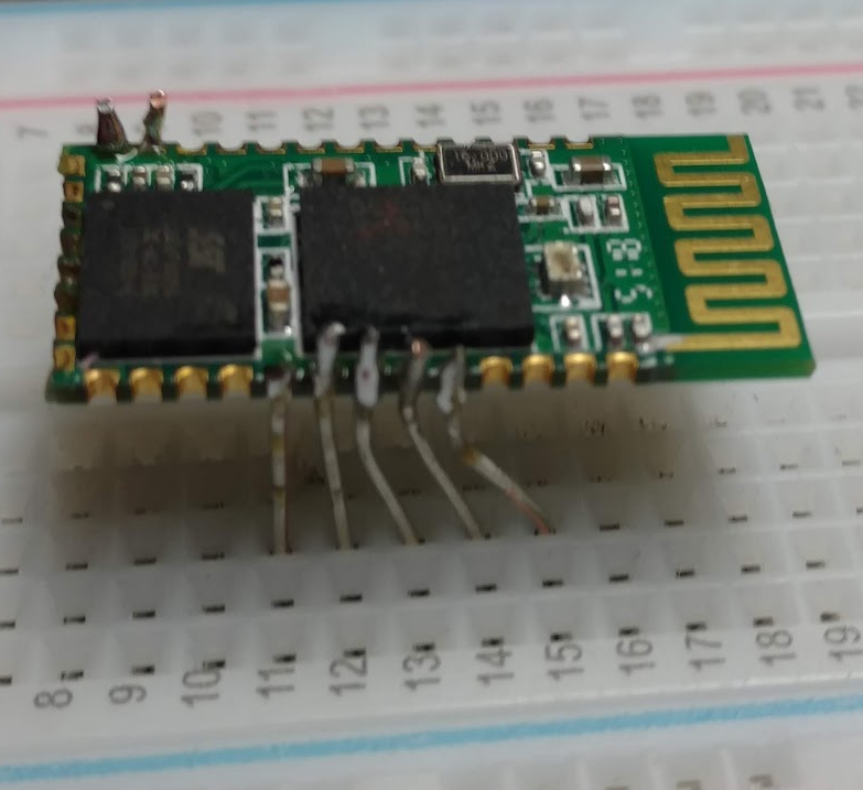 This worked better for me, and instead of attempting to pre-tin the board and wires, I just put a liberal amount of flux there and directly soldered with rosin-core much like how one would solder a header on a raspberry pi. One noticeable difference with this version of the chip it doesn't have an onboard LED. Last edit by VonBarth at 6 May 2019, 01:04 AM ------------- |
| [top] | |
| mit | Posted: 6 May 2019, 01:36 PM |
|
yeah whatever Admin Posts: 687 Joined: 4-May 16 |
Nice work. Yeah the original one I had didn't have an LED. On the plus side, that'll save you a teeny tiny amount of battery life. ------------- |
| [top] | |
| VonBarth | Posted: 12 May 2019, 03:12 PM |
|
-]Dream Machine[- Member Posts: 7 Joined: 30-March 19 |
Ok so this is what my new soldering job (and programming rig) looks like with leads on RX, TX, BTN, LED, VCC, GND, CLK, MISO, MOSI & CSB: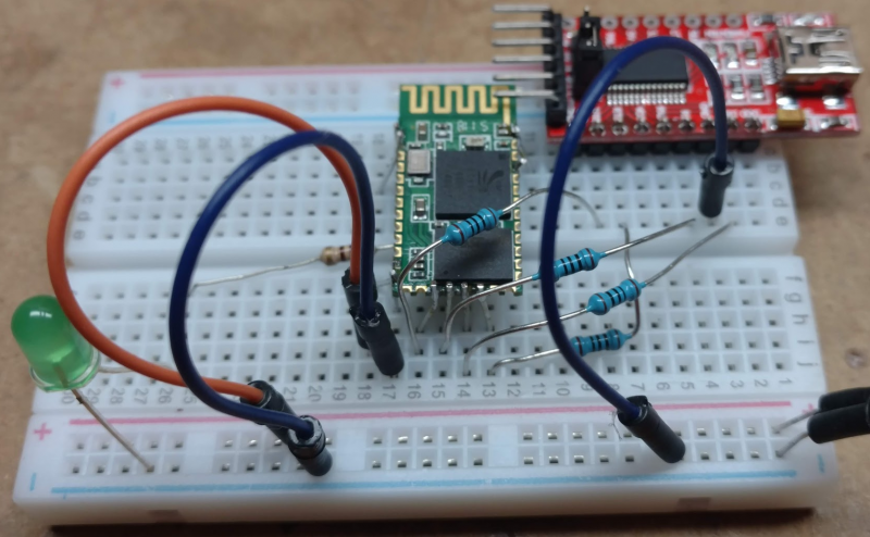 It works! I was able to dump off the stock firmware and persistent store and load the new, re-connect to serial and run the CMD bits easily thanks to your guide. I can pair to the device and the USB game controller (RNi Joystick) shows up exactly as in the guide, but I couldn't figure out how to send the test commands "0xFD 0x06 0x00 0x00 0x00 0x00 0x55 0xAA" - I'm planning on using an Arduino as my microcontroller so I'll have to get on with that bit now I suppose. Everything working great so far thanks to the project guide tho! ------------- |
| [top] | |
Sign in to post a reply.