« Previous • Next »Pages: 1 2 3 [4] 5
| timschu | Posted: 24 Jul 2022, 10:11 AM |
|---|---|
 Member Posts: 2 Joined: 23-July 22 |
FYI. You can read/erase/write the JDY-31 BK3231S flash with a CH341A programmer.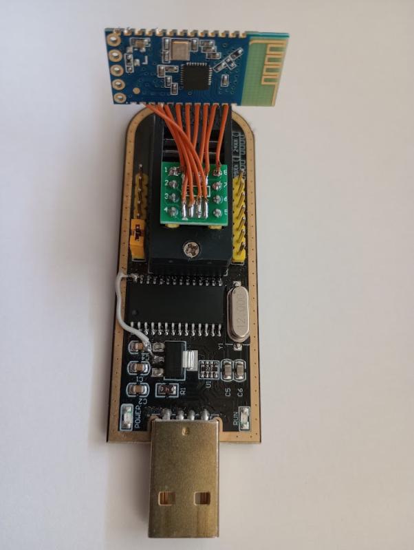 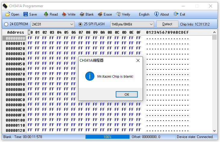 Last edit by timschu at 24 Jul 2022, 10:11 AM ------------- |
| [top] | |
| timschu | Posted: 24 Jul 2022, 05:16 PM |
|
Member Posts: 2 Joined: 23-July 22 |
BK3231 erase chip W 31 02 A5 W 31 03 C3 W 25 wait 100 ms W 31 02 00 W 31 03 00 erase sector W 31 02 A5 W 31 03 C3 W 24 aa aa wait 50 ms W 31 02 00 W 31 03 00 read 4 bytes W 22 aa aa R dd dd dd dd program 4 bytes W 31 02 A5 W 31 03 C3 W 21 aa aa dd dd dd dd W 31 02 00 W 31 03 00 "aa aa" is address / 4, high byte first "dd dd dd dd" is 4 bytes of data 1 sector is 0x1000 bytes, sector containing specified address will be erased JDY-30 BK3231 firmware is read-protected, returns FF FF FF FF ... :( MSB of programmed bytes 0, 4, 8, 12, 16, 20, 24, ... flip ~50% of the time, not sure why. Maybe BK3231 is not 100% compatible with my CH341A programmer. ------------- |
| [top] | |
| iscle | Posted: 12 Sep 2022, 10:44 PM |
 Member Posts: 6 Joined: 23-January 21 |
That's interesting! I had completely forgot about this thread/device but being able to talk to it with a CH341 is awesome! I'll play with it if I have some time in the future :D ------------- |
| [top] | |
| shenron | Posted: 26 Oct 2022, 04:34 PM |
 Member Posts: 1 Joined: 26-October 22 |
Hi, i bought a JDY-31 SPP-C. The chip on the PCB is a BK3431S. Do you think i could update the firmware to RN42 ? Can it be done with a Arduino Mega 2560 R3 or a Arduino Leonardo ? Do you know a good tutorial to perform the task ?  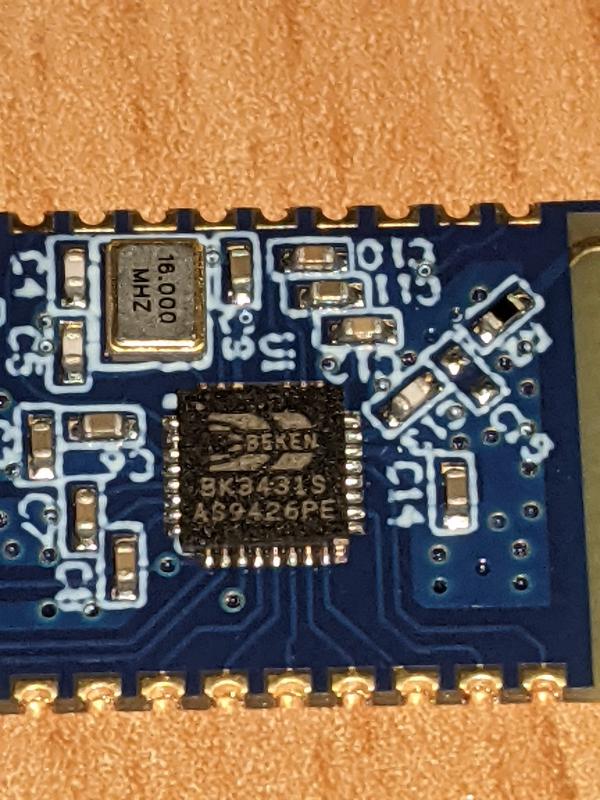 Last edit by shenron at 26 Oct 2022, 04:35 PM ------------- |
| [top] | |
| davidalfa | Posted: 26 Dec 2022, 05:59 PM |
 Member Posts: 1 Joined: 26-December 22 |
I wrote a script for the BK3231, using AsProgrammer so I could easily perform most operations with a CH341A. Read works, erase works, blank check works...but on writing, the verification fails every 32 bytes, so there must be something related to the CRC we're missing. Interestingly, tried writing random things, filling the entire flash with "Hi!!", the verification worked! Seems like the MSB bit (0x80) of every 32th byte means something! Additionally, it seems the maximum speed it can handle is 2MHz, which is pretty close to what the CH341A uses (~1.7MHz). I tested it with a BusPirate, at 4.5MHz it returned garbage. Here you have my FLASH DUMP. You will notice every group of 4 bytes is reversed compared to other backups. That's because they dumped it wrong, reversing the endianess! Even more strange, after erasing the flash and writing back the dump (Ignoring those errors), the device is working normally!
A capture from the logic analyzer:  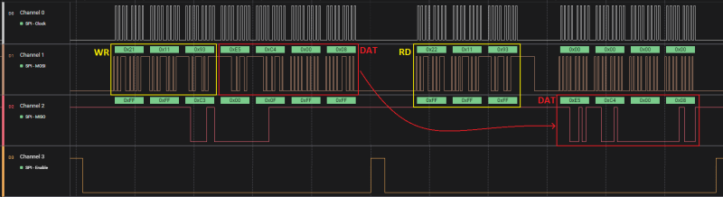 Last edit by davidalfa at 27 Dec 2022, 01:23 PM ------------- |
| [top] | |
| PookyFan | Posted: 11 Feb 2024, 11:21 PM |
 Member Posts: 8 Joined: 11-February 24 |
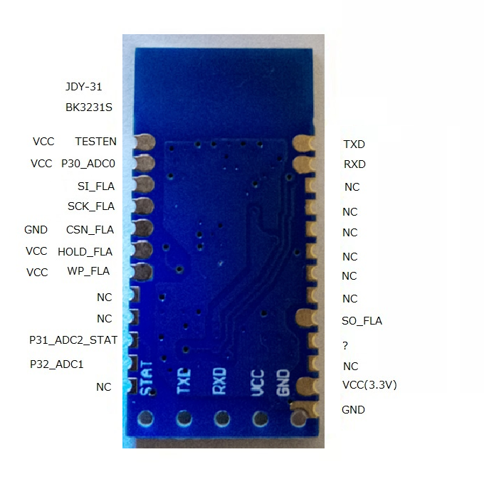
Hello. Just digging out this thread after over a year - don't mind me. I'm trying to figure out how to customize firmware on JDY-31 (the BT module with BK3231S MCU). There is some information on how to access its flash memory in this thread already, but there are some missing pieces, so I'd like to sum it up somehow, as I experimented with this module myself and as of now am able to dump the firmware. I am currently in the process of figuring out building custom firmware, and I'd eventually try to flash it and test how (if) it works. Let's start with connecting JDY-31 to SPI programmer. I personally use Raspberry Pi Pico as serial programmer, but any other 3V3 SPI programmer (like CH341A - just remember to have it modded!) should also work. On this thread's page 2 diizuka made pretty accurate assumptions on pins locations and how they should be connected: QUOTE (diizuka)
From my observations, however, it looks like you don't have to connect WP_FLA pin to VCC (you may leave it floating, connecting it to VCC doesn't seem to change anything). Also, instead of pulling CSN_FLA pin to ground, it's better to connect it to SPI programmer's CS line. So in the end, you should end up connecting JDY-31 pins like so: TESTEN => VCC P30_ADC0 => VCC HOLD_FLA => VCC SI_FLA => SPI prog MOSI SCK_FLA => SPI prog SCK CSN_FLA => SPI prog CS SO_FLA => SPI prog MISO Now BK3231S should be visible to SPI programmer as normal flash memory. For the purpose of reading its content, I'm using flashrom tool (available for all major OS like Linux, Windows or MacOS). 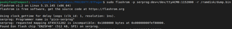 As you can see, flashrom detected it as EN25F40 chip with 512 kB of memory - that's rather plenty. The firmware doesn't take up entire flash, so large region at the end of it is blank (filled with 0xFF). Next thing worth noting (that was already spotted by others in this thread) is that every 32 byte of actual firmware, there are two bytes that turned up to be CRC (I'll talk about it later). So unless you do some cleanup, it would be hard to do ahything with it (in terms of reverse engineering). 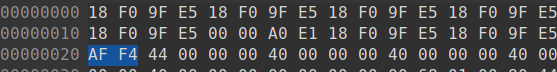 That would be it for reading MCU's firmware. Now we'd like to write our own and make JDY-31 do as we please. It turns out there is SDK available on Github for this chip (also posted earlier in this thread, by iscle). I haven't tried building it yet, but here are some interesting things about it.Turns out they actually pushed binary files together with the code. Among them are two files containing final firmware - "BK3231S_Test_Firmware.bin" and "BK3231S_Test_Firmware_crc.bin". And you've probably guessed it already, but the second one matches (at least its start does) firmware dumped from JDY-31's MCU. The first one, on the other hand, doesn't have CRC every 32 bytes. Looking at this project's configuration file, it looks like CRC version is prepared using some "encrypt" tool, which is unfortunately not included in this repo, but it's the one mentioned by diizuka: QUOTE (diizuka)
BTW, the misterious on 16 + 2 bytes is solved. Using this tool on non-CRC'd firmware file from the repository results in adding the same two bytes every 32 byte that are present in firmware we've just dumped. So now it's time to make use of this SDK and program JDY-31 with something more custom. But this is something I'm yet to deal with. I'll report any progress on that in the following posts. ------------- |
| [top] | |
| mr_woggle | Posted: 17 Feb 2024, 02:33 PM |
 Member Posts: 8 Joined: 17-February 24 |
@Pookyfun Thanks for all the info. I'm trying to repurpose a bluetooth tag with a similar chipset. 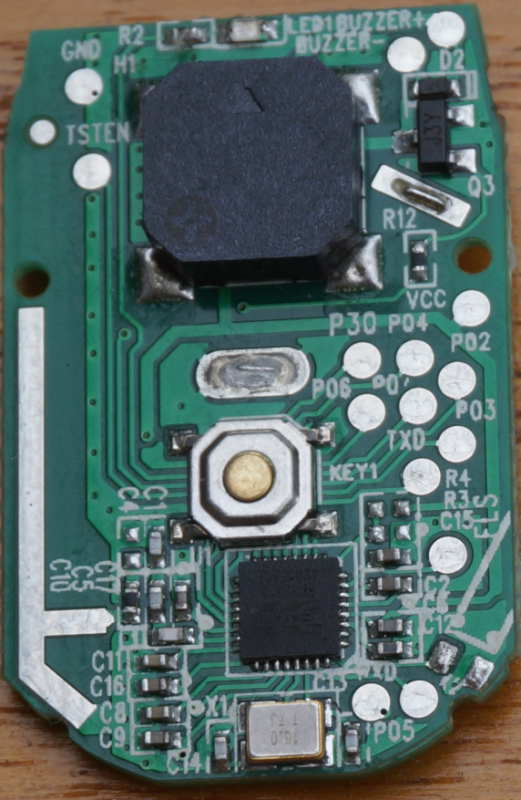 Took me a while to realise that this is S version. So there is no PPROG, but instead the TESTEN and P30 should are used and should be high to allow for read/write access. The SPI is very generic and any tool will suffice. (I used and ESP32 to read out the flash). And as you can see: 00000000: 18F0 9FE5 18F0 9FE5 18F0 9FE5 18F0 9FE5 ................ Next bytes are 0xAFF4 So same checksum on that. Any progress on the SDK / compilation efforts? ------------- |
| [top] | |
| PookyFan | Posted: 19 Feb 2024, 02:36 AM |
|
Member Posts: 8 Joined: 11-February 24 |
QUOTE (mr_woggle)
I only managed to get it to compile. That's already a big step, since the quality of the code is questionable at best. Plus its project was created and managed by some old uVision IDE version, and even outdated tool like that needs some kind of ARM license I obviously don't have. So I decided to migrate it to cmake project with GCC.Any progress on the SDK / compilation efforts? Even though it compiles, I'm still half way there, since I haven't corrected all compilation warnings yet (and I'd rather do that since, as I said, the code is of questionable quality). I also need to migrate assembly files which I didn't include into compilation process yet (the format differs slightly from GNU assembly used by GCC). Then migrate linker script so to make use of these assembly files setting up interrupt vectors and whatnot... Lots of work ahead of me. In the long run it may be worth to completely rewrite this SDK, but for the time being I just want to have something to flash my BT module with to test if it works fine. I'm also starting to have some suspicions about binary blob that is statically linked to the firmware (the BK3231S_LIB.lib file), it may be just some generic Bluetooth stack rather than close-to-hardware library, as I suspected it to be at the beginning. If it's just a BT stack thing, then it may be possible to replace it with something more open source (like btstack), but again - this is more of a long-run action to make firmware for BK3231S truly open source and of acceptable quality. ------------- |
| [top] | |
| mr_woggle | Posted: 19 Feb 2024, 11:53 AM |
|
Member Posts: 8 Joined: 17-February 24 |
QUOTE (PookyFan)
Even though it compiles, I'm still half way there, since I haven't corrected all compilation warnings yet (and I'd rather do that since, as I said, the code is of questionable quality). I also need to migrate assembly files which I didn't include into compilation process yet (the format differs slightly from GNU assembly used by GCC). Then migrate linker script so to make use of these assembly files setting up interrupt vectors and whatnot... Lots of work ahead of me. A lot of work indeed! Keep me updated on your efforts :) I'd love to join at some point. So according to the datasheet it *should have* JTAG. Although this is not specified. It's an ARM968E-S arch. Not sure where the TCK, TMS, TDI and TDO would be. It would kind of speed of debugging if that would be possible. Also found this evaluation kit board layout a while back: 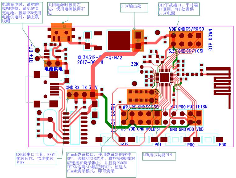 The OTP part (one time programmable for what?) at the right top also have CS, CK SI and SO. Mapping of pins is a bit weird though. ------------- |
| [top] | |
| mr_woggle | Posted: 19 Feb 2024, 12:49 PM |
|
Member Posts: 8 Joined: 17-February 24 |
QUOTE (PookyFan)
I'm also starting to have some suspicions about binary blob that is statically linked to the firmware (the BK3231S_LIB.lib file) ar -x BK3231S_LIB.lib Gives me only the (non-stripped) object files. 97K feb 19 13:24 bt_addr_sync.o This is 1:1 with the headers in src/Core /btj_src Seems to be some kind of ancient bt stack ------------- |
| [top] | |
| mr_woggle | Posted: 23 Feb 2024, 12:42 AM |
|
Member Posts: 8 Joined: 17-February 24 |
So, the so-called encryption is just a pretty standard 16-bit crc checksum, start value 0xFFFF, polynominal = 0x8005 The following code should reproduce the same output as the beken encrypt tool (not sure if they use this tool on other mcu/flash chips, or they have something more sophistecated in the mean time) Edge case is: if last chunk is less than 32 bytes it is filled with all 0xFF # by mr_woggle - 2024 Binaries are idential if I sdiff between the two. Last edit by mr_woggle at 23 Feb 2024, 12:43 AM ------------- |
| [top] | |
| PookyFan | Posted: 23 Feb 2024, 11:02 PM |
|
Member Posts: 8 Joined: 11-February 24 |
Wow, I was just investigating this, as it was the last piece to my toolchain (using blackbox .exe binary, especially on Linux, is hardly appealing). How did you figure it out? I'm very curious. ------------- |
| [top] | |
| mr_woggle | Posted: 24 Feb 2024, 12:56 PM |
|
Member Posts: 8 Joined: 17-February 24 |
Yeah, depending on those .exe files really suck. Similar to all those other flash upload tools. These companies somehow reinvent the wheel instead of just using something standard. For the hack: I encrypted an all zero binary. 2-bytes crc output is 0x8029 (after every 32 bytes like you said). Did not seem anything special or custum. So I went for the most common option, which is poly=0x8005 and some start value. You can just bruteforce the start values. And then check when the output is also 0x8029. (did not even had to that, because I just luckily picked 0xFFFF :D) You can write something yourself, but there are some cool tools out there (this one also has an overview of commonly used poly's etc) https://github.com/resilar/crchack
Some other chipsets of beken do use some sort encryption. I briefly looked at it. It uses 128-bit keys. So my guess is either AES or SM4 (chinese standard). Seems to have different outcome on consequetive blocks with the same data. So it is probably not ECB mode, but uses the outcome of previous block in some form. ------------- |
| [top] | |
| PookyFan | Posted: 24 Feb 2024, 01:06 PM |
|
Member Posts: 8 Joined: 11-February 24 |
Very clever, I haven't thought about that method you used. I allowed myself to grab your python code and use it in my post-build script (to hell with bash and external apps). This way I can easily transform binary from ELF into CRC'd build, integrated with default configuration blob (just took it from dumped firmware), pad it with 0xFF to have output image with size of the flash, and also have configuration at the right address in the image. So basically everything is ready. There is just one small problem: my image doesn't seem to work. Like, at all. I flashed it yesterday and seems it doesn't even reach main() (no output from UART, and yeah having working JTAG would help here a lot). I'll be investigating this today and hopefully resolve it ASAP, so that I could finally publish my port of this SDK for everyone to use (it's still crapload of poorly written Chinese code, but at least buildable without ARM's proprietary tools). ------------- |
| [top] | |
| PookyFan | Posted: 26 Feb 2024, 02:13 AM |
|
Member Posts: 8 Joined: 11-February 24 |
Allright, so there are some good news and some bad news. The good news is that I am pretty much done with porting original SDK, and have it now as CMAKE project hosted on Github. You can clone it, build it and test it for yourself, if you want. The code is still horrible and I only applied necessary changes to make it work (while not making it any better overall). Plus some minor changes for traceability, but these are really small. I built it with arm-none-eabi-gcc so I don't make any guarantee to it working with other compilers (CLANG for example, although I'm not sure if CLANG supports ARM anyway). And you'll need python3 to run post-build script (thanks again to mr_woggle for providing CRC algorithm). The bad news is that Bluetooth doesn't work at all. Everything else does though, or at least should - I only tested UART communication, but device also reads its configuration from flash properly, so I guess GPIO and whatnot should also be functionable. Although lack of Bluetooth kind of defeats the purpose of using this project, I'll be continuing with efforts to get it to work. If anyone would like to help, you are more than welcome, as this may be not easy for me to troubleshoot alone (majority of Bluetooth related code sits in the static library, so debugging it without JTAG would be a challenge, and most probably problem is either there or on the connection of the lib and SDK). To make it work out of the box, I put the configuration from firmware I dumped from my JDY-31 as binary blob that is merged with final image. Default UART config is 9600 baud, one stop bit and no parity. You can flash the image to JDY-31 using the same methods as for dumping original firmware from it. The flashrom tool I mentioned in my first post manages it without problem. It seems that the device needs to be powered off for a moment before it can run off with new firmware, though (to be confirmed). So yeah, that's it for now. What a weekend it was, trying to get it to work... ------------- |
| [top] | |
« Previous • Next »Pages: 1 2 3 [4] 5
Sign in to post a reply.