

« Previous • Next »Pages: 1 2 [3] 4 5
| iscle | Posted: 30 Jan 2021, 12:29 AM |
|---|---|
|
Member Posts: 6 Joined: 23-January 21 |
Hi tunnelrat, thanks for having a look at it! I haven't got my board yet so I can't test it. I'm guessing the tool is looking for a specific VID and PID for the USB programmer, and since it's not finding it, it throws the generic "busy" error. When putting the binary in Ghidra it was impossible for me to see anything useful, I haven't played with Windows x86 decompilation before... Only Linux for ARM and MIPS ------------- |
| [top] | |
| LeisureSuitLarry | Posted: 30 Jan 2021, 01:30 PM |
|
Member Posts: 4 Joined: 19-December 20 |
QUOTE (tunnelrat)
Hi tunnlrat, don't get confused by the external/peripheral SPI bus and the internal memory bus. The internal flash memory isn't connected to the peripheral SPI for several reasons, one of it is performance. Usually we don't have access to the internal SPI bus, but by pulling PPROG high, they kines get exposed to pins, which are not used by other SPI devices to avoid interferences (does that make sense?). This is an excerpt from the Sept-2014 data sheet V1.0.1 with the functional mapping of pins (which is hard to find!): 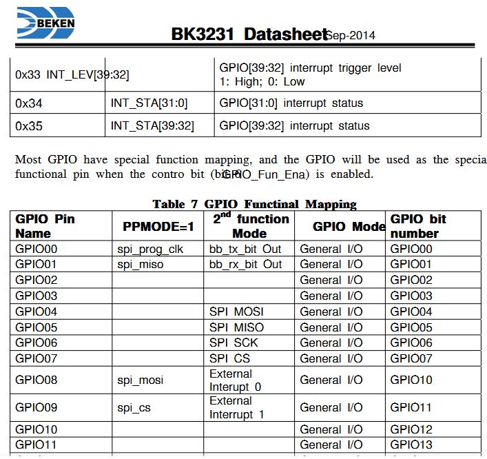 I was able to "talk" to the device in the mean time but get always the same response, so I'm still missing some details. According to teh earlier mentioned Chinese forum the procedure for accessing the flash memory via SPI is the same like for the flash programming via software. The registers indicated in the table below have to be used starting at 0. The procedure and registers to be used: 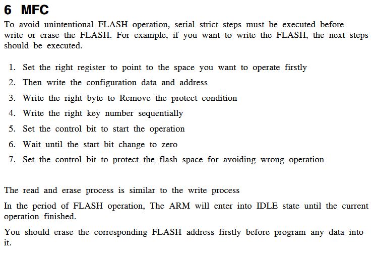 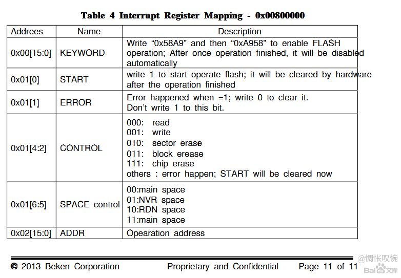 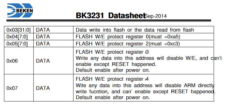 When I read back the registers I get '1' for all bits except for 0x01[0] and 0x01[1], where I get '0'. So in principle it seems to work soehow but not in the right way, since I can read back the first 2 registers (0 and 1) and then pattern repeats again. That means I can't read back registers 2 and 3. What I specifically don't know yet: do I need to write 32 bits / register? how to write to register 0x02 and further? It currently doesn't seem to work to start writing to 0x0 and continuing until all registers are written. data transferred back seems to be littleendian! I tried writing both ways but with the same result. I also tried the mentioned software (HID ...), but couldn't figure out yet which programmer to use. Has anyone an idea? Best regards, Larry ------------- |
| [top] | |
| tunnelrat | Posted: 4 Feb 2021, 11:21 PM |
|
Member Posts: 7 Joined: 17-January 21 |
QUOTE (iscle)
I'm guessing the tool is looking for a specific VID and PID for the USB programmer, and since it's not finding it, it throws the generic "busy" error. I tried to debug the program and find the ID by following the button click, but I gave up. I might revisit it soon. I have several projects going at once. Thanks for that clarification Larry. I'm glad you were able to get a copy with the functional mapping. Mine does not have that. I am getting the same response from my board as you are, so at least it's common. QUOTE (LeisureSuitLarry)
do I need to write 32 bits / register? based on diizuka's code: static void readFromFlash(uint32_t addr, uint8_t* buf, uint32_t length) {the address is 32 bit (0x00000000-0x0003FFFF), but it's sent to the flash in 8 bit segments, for MSB I assume, with an initial READ command 0b00000011. Something like: ADDR=00000000 00000000 00000000 000000000 At least I think that's what I'm reading. I've tried sending as 8 and 32 and get the same response. There's something else missing. I think diizuka was using a BK3231S, though. Maybe they are slightly different read processes between chips. This looks similar to the read method of another flash chip I was looking at recently. The CS pin was required to go high then low before it would respond, and this could be done with a pull up resistor according to the datasheet. I suppose that's not really an issue with GPIO programming. Again, I'm really new to this, and it's likely I'm making a mistake or 7 somewhere. Please tell me if I've made any mistakes in my evaluation. I'll post my logic analyzer capture the next time I try again. That download tool is probably the best bet if we can find an ID to work with. ------------- |
| [top] | |
| iscle | Posted: 22 Mar 2021, 11:57 PM |
|
Member Posts: 6 Joined: 23-January 21 |
After a bit of trouble, I was able to dump the entire firmware from my BK3231S module. It's here: https://drive.google.com/file/d/1cCyXjmhkq5Xfc9mps8s3FFp5jKZmd4rs/view?usp=sharing I was able to load it in ghidra and I see some strings which actually made sense, so it's a good readback. I haven't tried writing anything onto the flash yet. Last edit by iscle at 22 Mar 2021, 11:57 PM ------------- |
| [top] | |
| iscle | Posted: 23 Mar 2021, 06:55 PM |
|
Member Posts: 6 Joined: 23-January 21 |
Today I had a go at building the firmware on Github (https://github.com/AriesTian/BM3231) with Keil v5, and while it tries to compile it, it can't finish because there's one .lib file missing. The file is this one: src\lib\BK3231S_LIB.lib Maybe somebody can find it? I tried just ignoring it, and then the linker complies because it can't find some functions (which I guess were already closed-source even for authorized companies building on this platform). ------------- |
| [top] | |
| iscle | Posted: 1 Jun 2021, 02:04 PM |
|
Member Posts: 6 Joined: 23-January 21 |
Well, new update! I contacted the guy that had uploaded the source code to github, with the missing lib, and asked him to upload the lib too (and remove it from the gitignore). To my surprise, after a month or so, he replied and actually uploaded it! So we now have a fully working sdk. However, I'd like to reverse-engineer the .lib and create a fully open-source implementation of it. I still have to find a way to flash the firmware to the chip... ------------- |
| [top] | |
| tunnelrat | Posted: 6 Jul 2021, 03:27 PM |
|
Member Posts: 7 Joined: 17-January 21 |
Hey iscle. Thanks for your updates. Life has really gotten in the way of me experimenting with my boards. I think the main problem is that I have the BK3231 and not the BK3231S. The S chips have direct flash write protect and hold pins, where the non-S chips only have a program enable. I can't even get a flash dump to work properly. How were you able to dump yours? Did you get the download tool working? I'd like to dump one of mine, but I've never had any luck. If you have a new way of dumping the flash, I'll give it a try. ------------- |
| [top] | |
| NasAH | Posted: 22 Oct 2021, 12:10 PM |
|
Member Posts: 4 Joined: 22-October 21 |
By setting PPROG to “1”, the BK3231 internal FLASH memory can be read by SPI-slave. pin: 32 PPROG FLASH programming selection pin: 10 GPIO00 spi_prog_clk pin: 11 GPIO01 spi_miso pin: 21 GPIO10 spi_mosi pin: 3 GPIO11 spi_cs the protocol for reading: {0x22, addr_high, addr_low} - request for 4 bytes of data at addr {byte3, byte2, byte1, byte0} - response with 4 bytes of data ------------- |
| [top] | |
| tunnelrat | Posted: 11 Dec 2021, 05:33 AM |
|
Member Posts: 7 Joined: 17-January 21 |
Hi NasAH. Thanks for the info. I'm still unable to read from my chip. I get the same 8 bytes repeatedly returned. Do you have some code I can look at? I'm about ready to give up. I'm pretty sure I'm doing something wrong, but I'm running out of patience trying to learn. I just want to add a few more buttons to this box of bluetooth selfie sticks I have, but maybe it's just not meant to be. ------------- |
| [top] | |
| NasAH | Posted: 12 Dec 2021, 09:47 AM |
|
Member Posts: 4 Joined: 22-October 21 |
#include <sam4s.h> #include "spi.h" #include "bk3231.h" #define READ_W32 0x22 uint8_t cmd[9]; void bk3231_ReadBlock( uint8_t *var, uint8_t *dt ) { uint32_t i, n; uint32_t addr; cmd[0] = READ_W32; n = var[0]; addr = ( var[2] << 8 ) | var[1]; if( addr == 0 ) PIOA->PIO_SODR = PIO_PA0; // PPROG = 1 SPI_Enable(); for( i = 0; i < n; i++ ) { cmd[1] = addr >> 8; // addr_hi cmd[2] = addr & 0xff; // addr_lo SPI_Send( cmd, 3 ); SPI_Recv( dt, 4 ); dt += 4; addr++; } SPI_Disable(); if( addr == 0x10000 ) PIOA->PIO_CODR = PIO_PA0; // PPROG = 0 } ------------- |
| [top] | |
| NasAH | Posted: 12 Dec 2021, 10:03 AM |
|
Member Posts: 4 Joined: 22-October 21 |
OBDII mini BK3231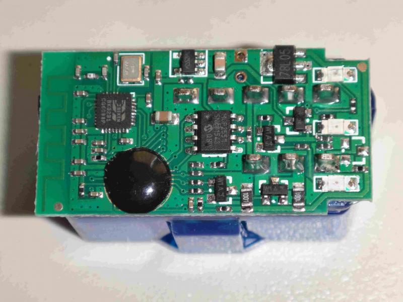 ------------- |
| [top] | |
| NasAH | Posted: 12 Dec 2021, 10:42 AM |
|
Member Posts: 4 Joined: 22-October 21 |
ODBII mini BK3231 dump https://www.dropbox.com/s/z2tpptcvuhm5wqv/obdii%20mini%20dump%20bk3231.zip?dl=0 ------------- |
| [top] | |
| tunnelrat | Posted: 15 Dec 2021, 12:41 AM |
|
Member Posts: 7 Joined: 17-January 21 |
Thanks for that NasAH. I'm going to have a look at everything soon when I get a free minute. Good to know it is possible to read these things. I hope I have some luck on my next attempt. ------------- |
| [top] | |
| tunnelrat | Posted: 19 Dec 2021, 02:07 AM |
|
Member Posts: 7 Joined: 17-January 21 |
Well, I've been trying again for the last few hours to get something to work, but have nothing but failure to show for it. After doing some more reading, I'm either still doing something wrong, which given how basic the read code is I really don't think that I am, or my chips have the lock bits set to prevent reading. Getting a repeating pattern response is supposedly a good indication that the lock bits are set, and that's what I keep getting. I guess I'm out of luck. I'll keep working on it and update if I get any new developments. I might try to erase one and see if I can read it afterwards. Thanks for the help, everyone. ------------- |
| [top] | |
| Gamer24 | Posted: 30 Mar 2022, 01:46 PM |
|
Member Posts: 1 Joined: 30-March 22 |
After some looking around on the github i found this it might prove to be useful in knowing how to get this programmer http://docs.bekencorp.com:8191/v3.0/get-started/download.html#spi-flasher 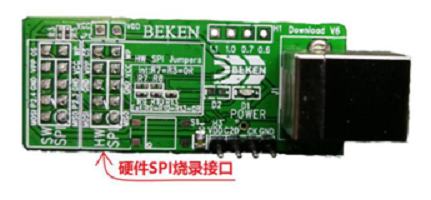 they are using this program mentioned in page 2 on this forum 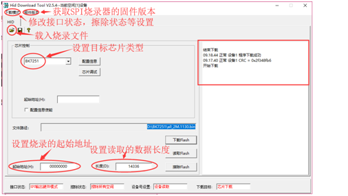 I will continue trying to get some info on this ------------- |
| [top] | |
« Previous • Next »Pages: 1 2 [3] 4 5
Sign in to post a reply.