
« Previous • Next »Pages: 1 [2] 3 4 5
| diizuka | Posted: 3 Oct 2020, 03:18 PM |
|---|---|
 Member Posts: 12 Joined: 18-September 20 |
Sorry, JDY-31 has BK3231S, not BK3231. JDY-30 has BK3231 itself. About JDY-30/JDY-31 module, I found some pads are wide. I suppose these wide pads should be used for wirmware writing. Using these wide pads are easy to contact metal terminals of writer. JDY-31: https://static-01.daraz.lk/p/9e61a86f261fd01b2b1c0026c990cde0.jpg_340x340q80.jpg_.webp JDY-30: https://ae01.alicdn.com/kf/Hdfeae91409364fb0b1a035c779992328K/JDY-30-JDY-31-SPP-C-bluetooth-HC-05-HC.jpg JDY-31 use "BK3231S QFN32 package(SIP with flash)". According to the BK3131S specification ( https://oss.aliyuncs.com/netmarket/f49abd45-0b36-460b-a160-e836d9da18b2.pdf ), These wide pads are for flash writing. BK3231S QFN32 pinout of JDY-31 widepads: chippin, func, note 12, WP_FLA 13, HOLD_FLA 14, CSN_FLA, SPI_NSS 15, SCK_FLA, MISO 16, SI_FLA, SPI_SCK 31, SO_FLA, MOSI 18, P30_ADC0 21, TESTEN 11, UART-TX 27, UART-RX 4, VCCMCU ?, GND Note: These pinout is differ from its SPI functionality. e.g: pin 15,16,31 BK3231 pinout of JDY-30 wide pads: chippin, func, description 10, P00, General I/O 11, P01, General I/O 21, P10, General I/O or interrupt active low 32, PPROG 3, P11, General I/O or input for external active low interrupt. 29, UART-TX 28, UART-RX 17, VCCDIG 24/31, GND PPROG should be high on firmware writing. In my opinion, pin 10/11/21/3 are for SPI SCK/MISO/MOSI/SC/WP/HOLD, but these correspondence are unknown. Perhaps, pin 21/3 has interrupt feature, these may be SCK. Pin 10/11 has normal GPIO feature only, these may be MISO/MOSI. Does anyone try to sole this funny puzzle ? You can get JDY-30 from Amazon, Ebay, Aliexpress(slow transpotation) Last edit by diizuka at 4 Oct 2020, 08:22 AM ------------- |
| [top] | |
| DAVID | Posted: 3 Oct 2020, 07:45 PM |
 I love mcus Member Posts: 237 Joined: 10-September 17 |
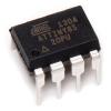
So, I have been seeing this post for quite a while and decided to finally contribute something. I have been searching for ways to program this SoC and I have found this post https://cloud.tencent.com/developer/article/1689683 In here the BK3431Q is used and after seeing the datasheet (http://www.fengqitec.com/file/bluetooth/BK3431Q%E6%95%B0%E6%8D%AE%E6%89%8B%E5%86%8Cv1.0.pdf) it seems that it also uses the 4 wire SPI programing interface. The problem is that in here a proprietary software tool is used  and also a programmer.  There is also this image  where it says that the bk5100 uses "Atmel Flash" memory so maybe that is a regular SPI flash memory. I might buy one of those Beken BK3231 modules to also start testing. Last edit by DAVID at 3 Oct 2020, 07:54 PM ------------- |
| [top] | |
| diizuka | Posted: 5 Oct 2020, 02:46 AM |
|
Member Posts: 12 Joined: 18-September 20 |
BK3231 dev board? PCB data. Coarse grain, hard to see. Does someone analyze where SPI Flash pins are ? https://wenku.baidu.com/view/b37f891fb42acfc789eb172ded630b1c59ee9b86.html# Seached from baidu.com "BK3231 hadware development(in chinese)" https://www.baidu.com/s?ie=utf-8&f=3&rsv_bp=1&rsv_idx=1&tn=baidu&wd=bk3231s%E5%9B%BA%E4%BB%B6%E5%BC%80%E5%8F%91&fenlei=256&oq=F-9688&rsv_pq=be4f049e0006a55e&rsv_t=0280ItcMND5LuM1JIRL4zasWBIQu2jrTlbyAdkl69LY3zgdKjTw30Mkbckc&rqlang=cn&rsv_enter=1&rsv_dl=ts_6&rsv_btype=t&inputT=36950&rsv_sug3=19&rsv_sug1=15&rsv_sug7=100&rsv_sug2=1&prefixsug=BK%2526lt%253B2%2526lt%253B1S%2520&rsp=6&rsv_sug4=36950 ------------- |
| [top] | |
| diizuka | Posted: 5 Oct 2020, 01:38 PM |
|
Member Posts: 12 Joined: 18-September 20 |
Pinout of JDY-30, JDY-31 Wide pads seems to be prepared for flash programming, because it can contact easily when it mount to the writer which have spring connectors for contacting pads. VCC/GND in left side of JDY-31 is my estimation connection on flash programming. 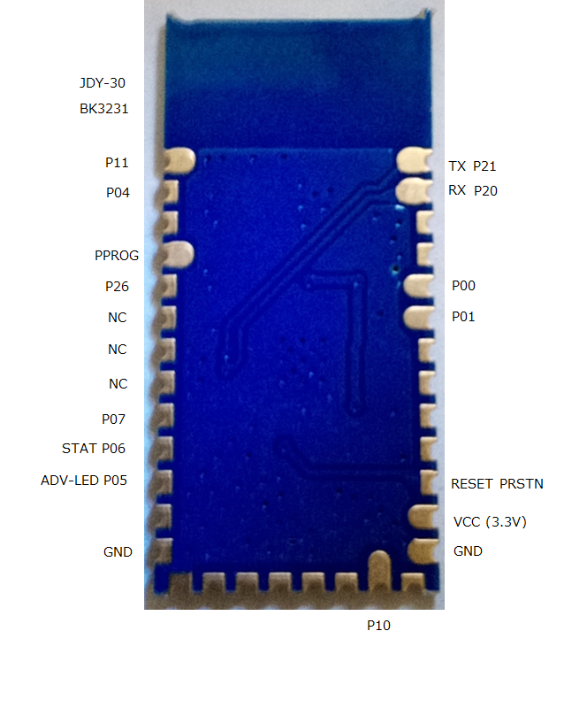 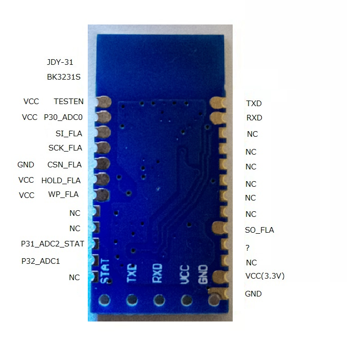 Last edit by diizuka at 5 Oct 2020, 01:48 PM ------------- |
| [top] | |
| diizuka | Posted: 8 Oct 2020, 04:00 PM |
|
Member Posts: 12 Joined: 18-September 20 |
I made it ! On BK3231S, I can read flash data, by using ESP8266 SPI I/F. - CSN_FLA should be controlled when operating to flash. - Wait for 10ms after BK3231S has powered on. Before waiting, I cannot read correctly from flash. - - Read identifier (0x9f) 1C 31 13. Which vendor does this flash memory ? - Read (0x03) I can read some data. But I don't disclose because of its copyright. First 32bytes seems to be reset vectors. ------------- |
| [top] | |
| diizuka | Posted: 9 Oct 2020, 02:52 AM |
|
Member Posts: 12 Joined: 18-September 20 |
Does anybody know about arm 32bit arch ? The first address of flash is reset vector: It jumps to somewhere. But its jump address is not aligned to 4bytes. I think this causes unalignment exception. Other vectors point to aligned address. addr(in hex) binary instruction 0: e59ff018 ldr pc, [pc, #24] ; 0x20 4: e59ff018 ldr pc, [pc, #24] ; 0x24 snip 20: 0044f4af // misaligned to 4 bytes 24: 00400000 // aligned to 4 bytes ------------- |
| [top] | |
| diizuka | Posted: 9 Oct 2020, 02:04 PM |
|
Member Posts: 12 Joined: 18-September 20 |
JDY-31 connect to ESP8266 via SPI. Wirling with UEW wire from JDY-31 pads to 2.54mm pich pins. 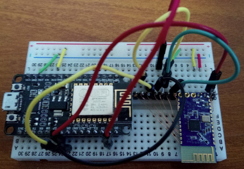
------------- |
| [top] | |
| mit | Posted: 9 Oct 2020, 04:53 PM |
 yeah whatever Admin Posts: 687 Joined: 4-May 16 |
Nice work! The first bytes of the firmware will be the interrupt vectors. There are lots of different ARM architectures. Importantly "thumb" instructions are only 16 bits. Full size ARM chips can switch between 32bit instructions and thumb instructions, but some microcontrollers only support thumb. If it's jumping to an address that's not aligned to 32 bits it's probably thumb. I just looked at the datasheet for the BK3231S, the processor is ARM968E-S, which supports both 32-bit and thumb instruction set: https://www.hwlegend.tech/wp-content/uploads/2011/01/DDI0311.pdf ------------- |
| [top] | |
| diizuka | Posted: 10 Oct 2020, 02:36 AM |
|
Member Posts: 12 Joined: 18-September 20 |
Thanks mit. I found that for each 16 bytes, 2 byte dummy/garbage/checksum data exists. By omitting these dummy data, the disassebled code seems to be correctly. Sometimes thumbs codes are used. How to disassemble arm firmware: - I use Debian. It may work on Ubuntu. - convert HEX string to binary using the following python3 code. Give hex string to stdin. #!/usr/bin/python3 - sudo apt-get install binutils-arm-none-eabi - arm-none-eabi-objdump -D -b binary -m arm > arm.disasm - arm-none-eabi-objdump -D -b binary -m arm -M force-thumb arm.bin > arm.disasm.thumb Dummy data calculation method is needs when writing custom firmware. Last edit by diizuka at 10 Oct 2020, 01:58 PM ------------- |
| [top] | |
| diizuka | Posted: 11 Oct 2020, 07:33 AM |
|
Member Posts: 12 Joined: 18-September 20 |
I made a mistake of previous post: Wrong: for each 16 bytes, 2 byte dummy/garbage/checksum data exists. Correct: for each 32 bytes, 2 byte dummy/garbage/checksum data exists. BTW, the misterious on 16 + 2 bytes is solved. encrypt.exe adds 2bytes CRC for each 32 bytes. https://github.com/cornrn/bk7231_freertos_sdk/tree/master/tool/crc%20binary encript.exe CRComitted.bin 0 will generate same binary got from flash. Last edit by diizuka at 11 Oct 2020, 02:54 PM ------------- |
| [top] | |
| LeisureSuitLarry | Posted: 19 Dec 2020, 04:59 PM |
 Member Posts: 4 Joined: 19-December 20 |
QUOTE (diizuka)
Pinout of JDY-30, JDY-31 Hi guys, If anyone likes to try to readout the BK3231 flash (not the BK3231S), then use these connections as per the latest datasheet: P0 --> CLK P1 --> MISO P10 --> MOSI P11 --> CS However, you may not be able to readout anything usefull, because the code can apparently be protected against readout by writing a special sequence into the last 4 bytes of memory. Another pitfall is, that P10 may not be available on some boards, so you would need to make contact to the chip directly. I tried with several tools to readout the memory of some boards I have and all lines seem to react correctly, but the result is 0xFF for most of the memory cells. Maybe someone else is luckier than me. Couls also be, that the read commands are different to what is commonly used. Have fun ... ------------- |
| [top] | |
| LeisureSuitLarry | Posted: 24 Dec 2020, 12:16 PM |
|
Member Posts: 4 Joined: 19-December 20 |
Hi all, some more information can be found on a chinese website/blog: https://zhidao.baidu.com/question/494943407848948452.html (It is also worth opening the spoiler in the top left corner below the head line! Translate with google and guess, what is meant ;-)) It seems that the addresses given in the data sheet are register numbers and we should have access to the them via SPI. Should the information be valid, then we can only access the flash dword by dword and we need to follow the same procedure as defined for internal access via MFC (same sequence, same keywords, ...). I wasn't able to get the chip to respond so far. It just stops running the program, when PPROG is raised. Open questions to me are: - is CS active low or active high? I assume it is active high since the pin itself is near ground when PPROG is raised to 3.3V. - are the registers 16bit or 32bit wide? I assume we need 32 clock pulses for each register since the data in register 4 is 32bits wide. - which SPI mode should be used? Since the chip's MISO pin didn't respond at all so far, there is no way for me to check. Maybe someone else is able to open the box with this information ... Best regards, Leisure Larry ------------- |
| [top] | |
| tunnelrat | Posted: 17 Jan 2021, 06:08 PM |
 Member Posts: 7 Joined: 17-January 21 |
Hello everyone. I'm also trying to reconfigure a BK3231, but in a different setup. I have several selfie stick buttons that I'd like to repurpose into custom bluetooth controllers. QUOTE (LeisureSuitLarry)
If anyone likes to try to readout the BK3231 flash (not the BK3231S), then use these connections as per the latest datasheet: Larry, I'm confused about this statement. The datasheet that I have shows this for what you listed: 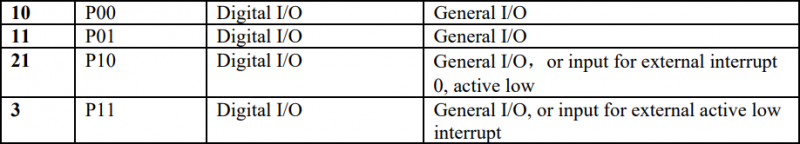 And it shows this as the SPI pins:  Your pinout does make sense though given the button looks like this: 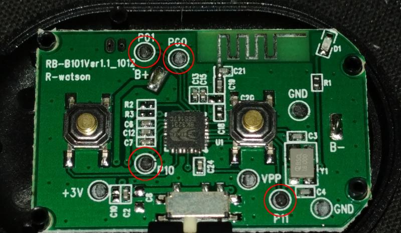 The datasheet that I have has "Sep-2014" at the top. Do you have a newer rev? I'm going to see if I can get this button to talk to me using the pinout that you listed since it matches the pads on the board. I believe I have to pull the VPP pad high to do that. I'll have to read through the thread again to make sure. If I make any progress, I'll let everyone know. I know diizuka was able to read from the boards you guys have. Maybe I'll have some luck on mine. ------------- |
| [top] | |
| iscle | Posted: 23 Jan 2021, 01:08 AM |
 Member Posts: 6 Joined: 23-January 21 |
Hello everyone! I just registered on this forum to, hopefully, shine some light to the project. I have found the download tool for lots of Beken MCUs (including BK3231 and BK3231s!). It was actually "hidden" in their GitHub! This is the file: https://github.com/bekencorp/bk3633_mesh_sdk/blob/master/download_tools/%E7%83%A7%E5%BD%95%E5%B7%A5%E5%85%B7.rar 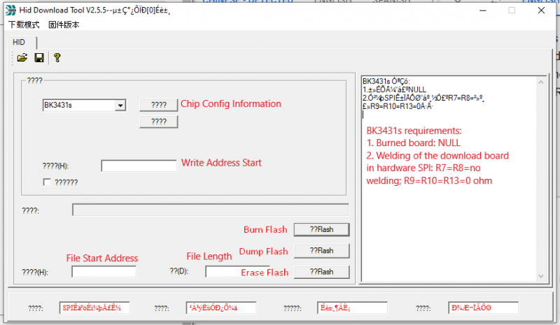 I don't have the module yet, but if anyone wants to play with it I'm sure we'll get somewhere :) Last edit by iscle at 23 Jan 2021, 01:51 AM ------------- |
| [top] | |
| tunnelrat | Posted: 29 Jan 2021, 04:18 AM |
|
Member Posts: 7 Joined: 17-January 21 |
I grabbed the download tool. Thought I might have some luck on my board with it. Here it is with the Unicode converted to Chinese if anyone wants to translate. I used the Google translate app on my phone with a live translation though the camera to read it. It's pretty much the same as what's in iscle's post.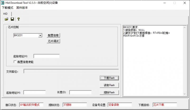 I had my USBtiny programmer connected to my computer hoping it would suffice, but I get this error. It says something about the device being busy, which is probably a default message about a missing driver or device. 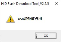 I also tried to decompile it to see if there was anything in there readable about the flash read method and failed miserably. I've been able to talk to my boards through my raspberry pi, but I'm not getting anything useful. Flashrom detects the flash, but it says the flash is "not working" and can't read it. My python script is returning a repeating sequence of "ff ff ff ff 00 00 0f ff ff ff" (might be more or less 'ff's) no matter how many bytes I read. I'm pretty new to SPI and directly accessing the flash, so I'm probably doing something wrong. I probably should have started somewhere simpler. ------------- |
| [top] | |
« Previous • Next »Pages: 1 [2] 3 4 5
Sign in to post a reply.