
| aleok | Posted: 22 Sep 2024, 04:50 PM |
|---|---|
|
Member Posts: 8 Joined: 31-July 24 |
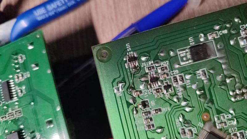
Good evening to you all, Recently I got my hand on a broken Alesis Photon X25 along with another MIDI keyboard for cheap. I spent most of my saturday fixing and cleaning the thing. The issue with the keyboard was that, although plugging it via USB did trigger a windows USB plug-in event, the message seemed completely wrong - The VID (or PID, can't remember well) was set to 0xFFFF, and it didn't even register as a MIDI input device. As a side effect, the keyboard seemed completely dead - No LCD nor button backlights. I suspected a microcontroller fault of some sort. I disassembled everything and found the datasheet for the uC (Some silicon labs chip, not very relevant) and found out that it was getting a measly 20mV into its single VCC pin. It expected 3.3V. After some continuity checking I found out that the VCC trace went to a connector that went into the power supply board, which also housed the USB connector and controller. When I disconnected the uC board from it I could measure around 0.5V through the according connector pin in the PSU board. Somewhat bizarrely though, the single 3.3V source available (A LDO) was working completely fine along with the USB controller. And so here's the problem. The regulated 3.3V was going into the source of a N-channel MOSFET, with the gate being 5V from some complicated circuitry (which, from its level, can be deduced that it somehow connects to the USB power lines), and the drain powering up the faulty 0.5V VCC pin. My only theory here was that the MOSFET is broken. I bridged the drain and source lines since I didn't have a replacement transistor, and after connecting it to my PC, it sprung back to life - Hooray! Sadly however it only works sometimes when plugging it in. Other times it does the exact same thing as before - Unknown PID/VID, no backlights. I come here asking for a possible reasoning to this mystery that still has me puzzled - What could this MOSFET circuit possibly do here? Is it possible that only this transistor could fail? Is it possible that the current spurious failings are caused by me not changing the transistor and instead bypassing it? My personal theory, after having assembled the entire thing together again, is that this transistor is somehow controlled by the USB controller. It would dictate the power-on sequence and since the MOSFET is now essentially a bridge only sometimes the sequence is correct when plugging in the keyboard. Let me know your thoughts and speculations though, any bit of info (Specially about a possible replacement FET) is greatly appreciated. BTW - Having a forum like this is great. It's like a breath of fresh air away from all the megacorps that surround us - Thank you Tim :) Attached is the botchy repair I did bridging the drain/source of the faulty MOSFET.  Last edit by aleok at 22 Sep 2024, 08:04 PM ------------- |
| [top] | |
| mit | Posted: 23 Sep 2024, 02:06 PM |
|
yeah whatever Admin Posts: 657 Joined: 4-May 16 |
I'd need to see the whole schematic to give an informed opinion, but here are some ideas. If it's enumerating but with an unexpected PID/VID, it might be some bootloader mode has been triggered. Often to do a firmware update, you power on the device with some hardware condition like holding down a button, which runs the bootloader for firmware updates, or some other recovery mode. If that's the case, it might be a dodgy switch somewhere is the cause of everything. If it has a separate controller for the USB then it might not be that. If it has a part number see if you can find any info on how it works. QUOTE
Are you sure? usually with N-channel current goes into the drain and comes out from the source. P-channel is the other way. If it's a P-channel high-side switch then it's activated when the gate goes low. The 5V you're seeing may be a pullup to the usb vbus.The regulated 3.3V was going into the source of a N-channel MOSFET A good debugging option if you have access to it is a thermal camera, see if any parts are getting hot. Often if a capacitor has failed, a regulator may not be stable any more, so it might operate OK sometimes and other times it will latch up entirely. ------------- |
| [top] | |
| aleok | Posted: 23 Sep 2024, 08:20 PM |
|
Member Posts: 8 Joined: 31-July 24 |
Hello, thank you for the insights :) I'll reply in-line: QUOTE (mit)
Unfortunately I could not find any on the internet :( It's the first thing I tried to search for.
QUOTE (mit)
Maybe I haven't explained myself correctly (sorry!), the keyboard has a board housing the USB connector (As well as some other ports, like a DC input jack and a switch to change between both) and a USB controller IC. This is what I referred to as the power supply board. The microcontroller is actually placed in another board, which connects to this previous board as well as other ones (the actual keyboard, front buttons, sliders, etc. If it helps, the microcontroller is a Silicon Labs C8051F31x and the USB controller chip is a Texas Instruments TAS1020B.If it's enumerating but with an unexpected PID/VID, it might be some bootloader mode has been triggered. Often to do a firmware update, you power on the device with some hardware condition like holding down a button, which runs the bootloader for firmware updates, or some other recovery mode. If that's the case, it might be a dodgy switch somewhere is the cause of everything. QUOTE (mit)
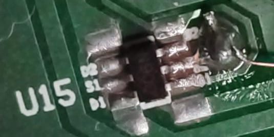
As long as the PCB silkscreen is correct and I probed correctly, it should be connected to the source of the MOSFET, yes. However, it is true that I kinda speculated on the N-channel part - The package has "306N" etched onto it. Apparently the image got downscaled or compressed when uploading it (the photo itself is pretty bad because I didn't think I would be using it later on as a reference, oh well). Here's a zoomed-in cropped version of the original image detailing the silkscreen and package:
 It's hard to see, but the text says the following:
?? is where the 3.3V of the LDO directly connect. Since the only pin not taken is S2 I assumed it's a source. The faulty uC rail connects to D2, and the pull-up 5V to G2. QUOTE (mit)
Hmm, that makes much more sense. Don't you think 0.5V is a bit too high of a voltage if the transistor is inversely polarized though? Either way I'll have to check where exactly this gate connects to to see what controls it - Maybe the issue lies there.
QUOTE (mit)
I've seen people use thermal cameras for stuff like this - But I just assumed they were just too expensive for my budget. I'll see if I can get one from my workplace's lab though, maybe they have one. The power supply board by itself only draws 0.3W when plugged in, so I think it's going to be hard to see anything heat up... But we'll see. Thanks for the idea!
I won't be able to give more detailed information until Friday, since I don't have the keyboard here right now - But I'll still keep answering whatever I can until then, and any other ideas are more than welcome :) Last edit by aleok at 23 Sep 2024, 08:59 PM ------------- |
| [top] | |
| mit | Posted: 25 Sep 2024, 02:49 PM |
|
yeah whatever Admin Posts: 657 Joined: 4-May 16 |
That USB controller has a processor in it, which has a firmware update mode (DFU), I just googled it and the datasheet mentions "a Vendor ID of 0xFFFF and a Product ID of 0xFFFE is reported" in DFU mode. The problem probably still is with the power/startup sequence as you were thinking, just maybe the lack of communication from the host processor leaves it in update mode. I only quickly glanced at the datasheet but it might be worth reading through it. QUOTE
I don't quite follow, but just look up the normal way of wiring a high-side switch with a p-channel mosfet. Look carefully at the labels for drain and source. Normally a p-mosfet turns on when the gate is pulled low.Don't you think 0.5V is a bit too high of a voltage if the transistor is inversely polarized though? ------------- |
| [top] | |
| aleok | Posted: 19 Oct 2024, 07:43 AM |
|
Member Posts: 8 Joined: 31-July 24 |
Hey, chiming in to say that the issue got fixed! I looked at the boards with a thermal camera and to check whether the transistor was the issue I cut the wire I soldered. That immediately fixed the issue 😅 My professor says that maybe the original issue was a cold joint which I inadvertently fixed by soldering the wire. While it is still not fully fixed (Can't get the pitch/mod knobs to work and the AXYZ control does not seem to respond either) it's still good progress I think :) Thanks for your help! If you hadn't suggested to check it with a thermal camera I probably would have never cut the wire. ------------- |
| [top] | |
Sign in to post a reply.