
Eurorack Knob Idea
24 Apr 2025Progress: Complete
Last year I designed a eurorack module, as a collaboration with Dave Cranmer. When I say designed it, I mean we got about 90% of the way there, then got distracted. With any luck, that module will get finished and released sometime soon.
But it had me thinking about Eurorack and the weird compromises people often make to fit more and more modules into a tiny case. I know a thing or two about tiny synthesizers. But my creations are often whimsical and useless. When it comes to Eurorack, where people spend crazy amounts of money on their setups, it's weird to see people compromise on the main aspect that gives it an edge over simulating the whole thing in software.
To clean up our Eurorack panels, perhaps we need a new knob idea? Watch the following video for a prototypical demo.
In essence, we're using a 3.5mm jack in front of a magnetic encoder chip, and a small magnet embedded in the plug turns it into a knob and patch cable hybrid.
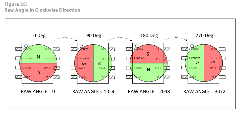
The magnetic encoder in question is an AS5600. These are not the cheapest parts but they do make prototyping very easy. It has two hall sensors in an XY configuration and a dollop of DSP to give us an angle and a magnitude. They're easily available on breakout boards and have an i2c interface.
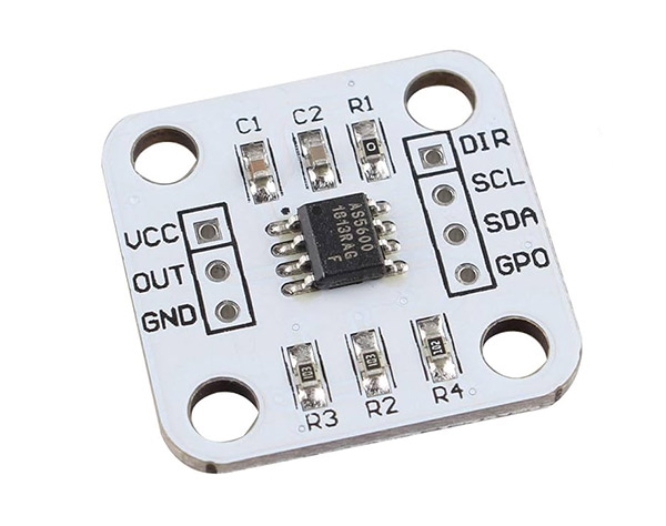
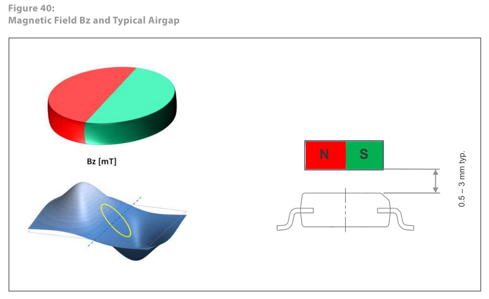
The board also comes with a specially polarised magnet with the field across the diameter instead of axially. We're not going to use that.
Building the knob
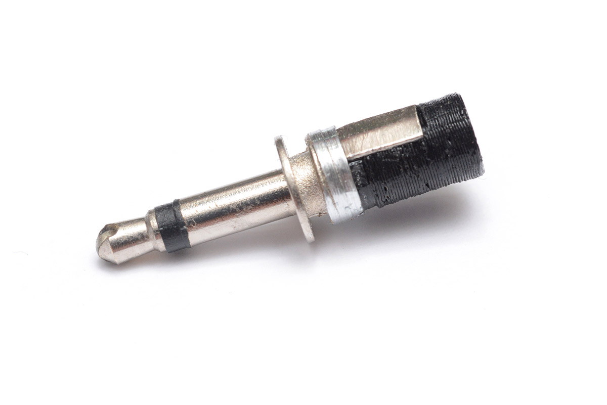
I started by taking a dremel cutting disk to the end of a TRS plug. This was just done by eye. Edge-on, it's not quite centred but it'll work fine.
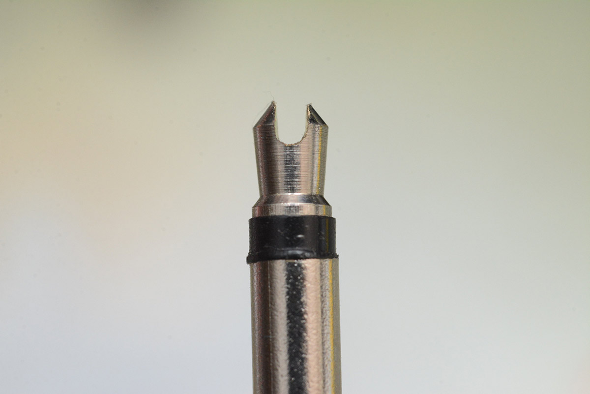
This cheap plug is in fact partially hollow, and is made from plated brass.
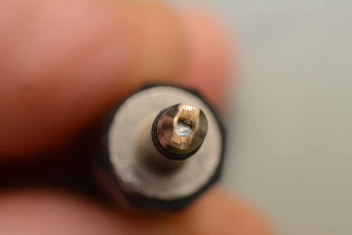
Into this slot I glued a small neodymium magnet. It's 2mm diameter, 1mm thickness. I also bought some 2mm thickness magnets, but that would need a slightly wider slot, which would probably require a more precise cutting method.
I used a medium viscosity cyanoacrylate glue. Once set, the excess can be scraped away with a razor blade.
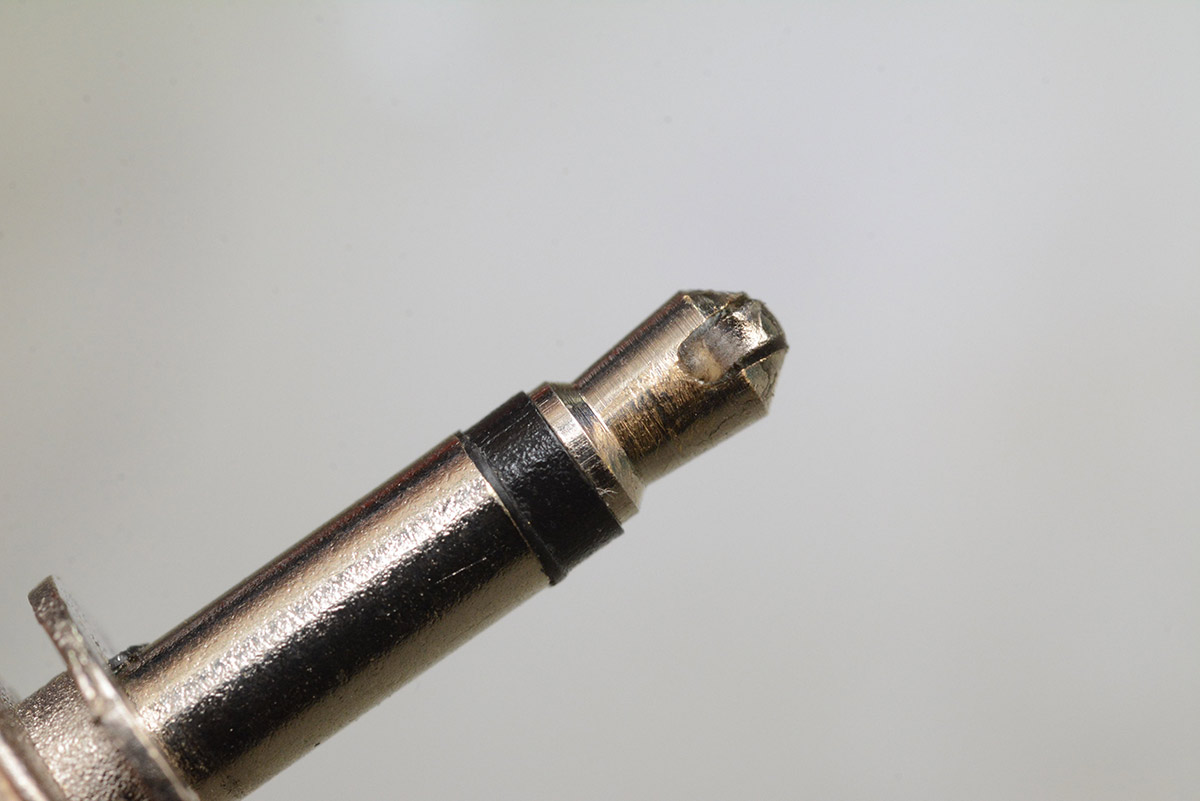
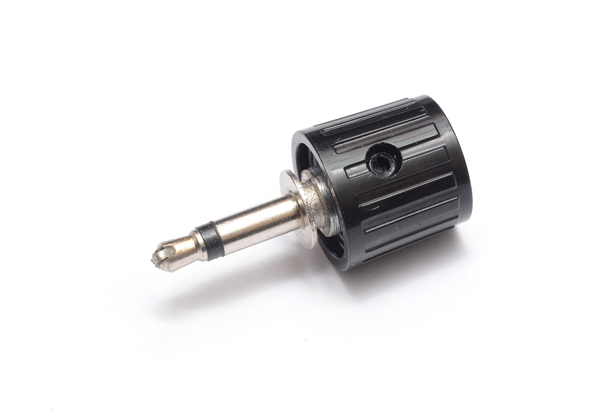
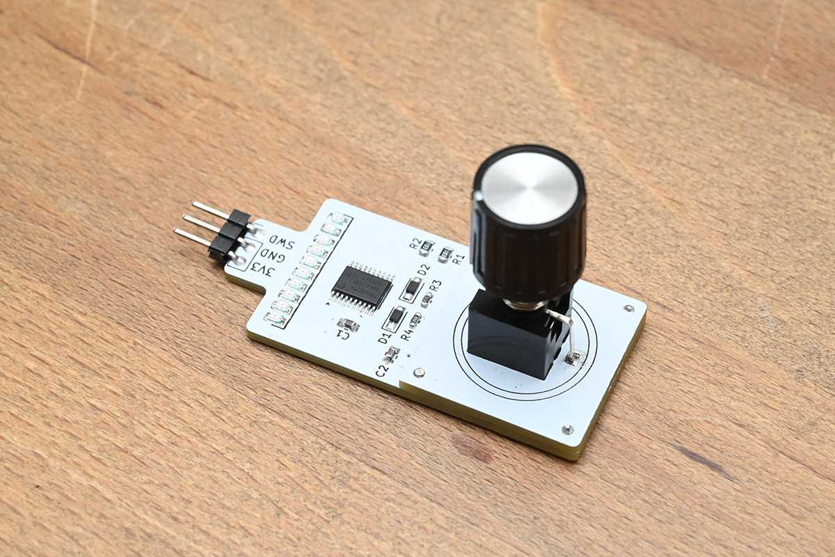
I turned away the threaded section, trimmed the metal tab, and 3D printed a filler piece so the back of the plug is just a straight cylinder to which we can fit a knob.
And to that, we fitted the knob. The 3D printed plastic is quite pliable, so the set screw embeds itself a little and gets a solid grip.
Circuit design
I was unsure if the tiny magnet would be sufficient, and how close it would need to be held to the soic-8 sensor chip. I did some tests, just holding this magnetic knob over one of the breakout boards.There's both a PWM output and a DAC on the AS5600, with the idea that we can use it, once configured, to output an analog voltage. I had a assumed there was some zero-config mode that would just turn magnetic fields into voltages, but it seems we need to set it up via i2c to get any output. If that's the case, for the sake of this test we might as well just read out the angle via i2c as well.
After a few experiments I was convinced it was going to work, so I set about building a circuit board that could house the AS5600 under a TRS socket.
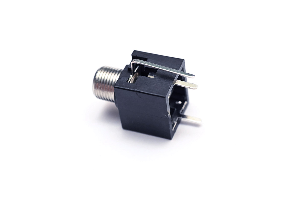
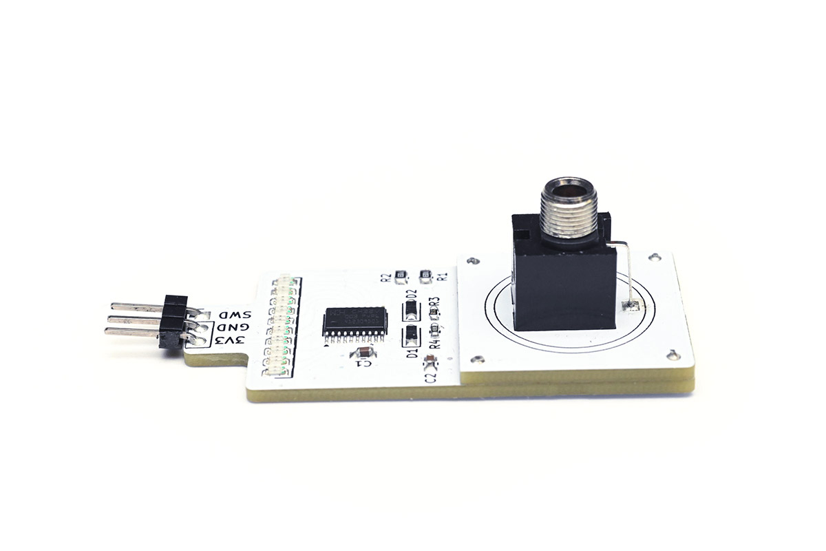
A common style of vertical-mount TRS socket looks like this (I believe it's a PJ398SM):
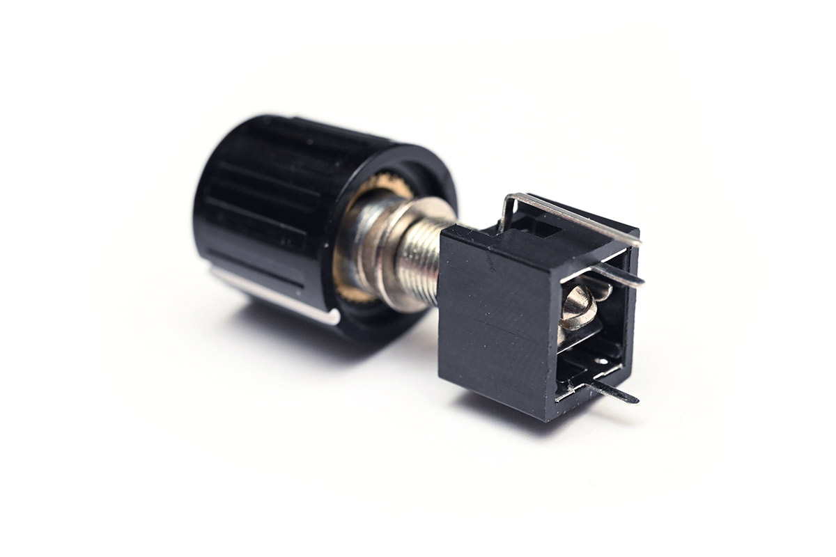
With our magnetic knob fitted, we can see that there's almost zero clearance between the tip of the TRS plug and the plane of the circuit board.
There might be a vertical-mount TRS jack out there somewhere that has enough clearance underneath it, but the through-mount pins are long enough here that we can just lift up the socket off the board. I considered 3D printing or laser-cutting a frame to elevate it, but better still is to use PCB material (FR4) as we can tack it onto the same circuit board order.
The height of the AS5600 is about 1.47mm; a 1.6mm board will work nicely. There are some diagrams in the datasheet illustrating how the magnet should be situated relative to the chip.
I stacked the two part footprints, and then laid out a second version of the socket footprint with a cutout for the chip.
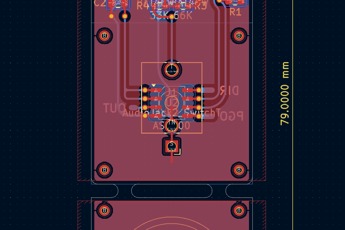
I like to model the board outline exactly, with a 2mm endmill in mind, it makes it explicitly clear what we expect to receive from the board house. If you specify tight inside corners, they will probably use their judgement as to how tight a corner you were expecting. Drawing these out in KiCad is a bit tedious, but at this point I'm used to it.
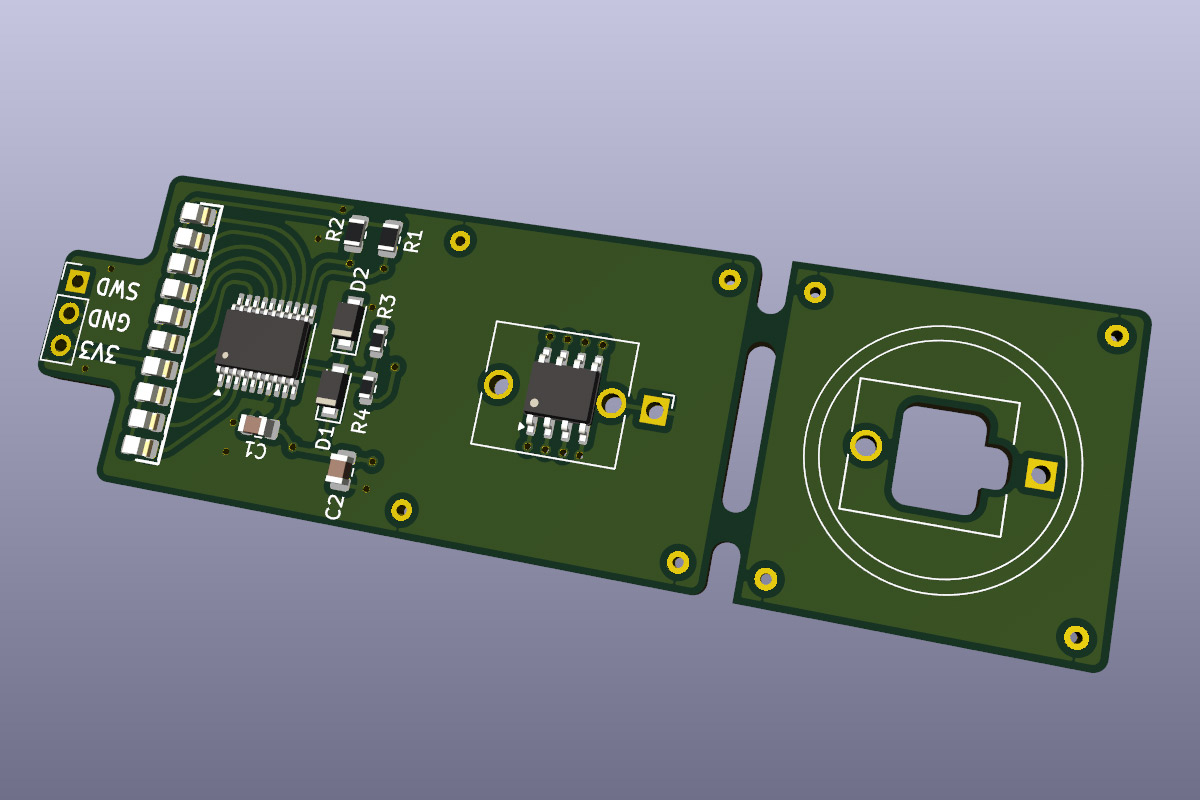
I optimistically added a CH32V003 and a bunch of LEDs so we can show the value. I also chucked the usual clamping diodes and ~100K input impedance, made of 33K and 66K resistors, which divide a 0-5V signal down to 0-3.3V.
Since the encoder chip will be buried, I also added pads underneath so that if it comes to it, we can probe any leg of the chip.
The design was blasted off to China and a short while later the boards were in my hands.
Assembly and test
Assembly was uneventful. I was especially careful to get the AS5600 perfectly centred on the pads.I broke off the lower part of the board, filed the tabs flush, and fitted it over the top half using the possibly superfluous alignment pins, into which I soldered some bits of wire.
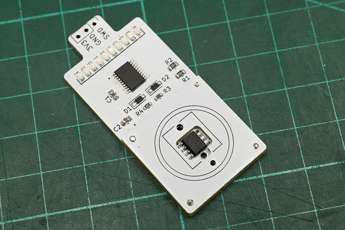
And then we solder the TRS socket on top of that.
It is a little tricky to capture the white board on a white background.
Programming the CH32V003 was routine. A little massaging of the i2c, coaxing up the ADC, graphing on the LEDs, eye of newt and Bob's your uncle.
The encoder chip reads the field strength, and we can use this to detect the presence of our knob. I had wondered if ordinary patch cables would have some stray magnetism but they seem to usually be made of nonferrous metals. Anyway, when our knob is connected the strength reads around 2000 units, on a scale of up to 4095. Ordinary cables read zero or occasionally 1, so I don't think there's any ambiguity. Marvellous.
Conclusion
I'm pretty pleased with how the prototype turned out, but I also don't expect to take this any further.
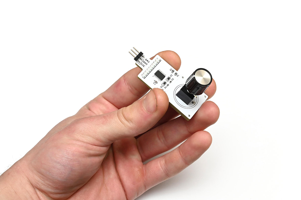
It's a nice dream, of a synthesizer where any knob can be pulled out and replaced with a patch cable, and any jack can have a knob plugged into it to set it to a fixed value. Whether it's actually practical to build a synth like this I'm unsure. It would probably only be worthwhile if you applied it to every single control on the modular, which rules out using other people's modules. You would have to invest heavily into the Eurorack Knob Idea. You couldn't even port other modules that easily, as many of them would expect a real potentiometer, whereas the encoder can only produce a voltage. Coupling it with a voltage-controlled potentiometer would work, but would be even more expensive.
I'm starting to envision a cult of Eurorack Knob Idea Enthusiasts, or Euroknobists: those who only build modular synths with the Euroknob principle. It's a beautiful dream – a very expensive, but beautiful dream.
The first few people I showed this to insisted I should patent it, but that's a costly process that I just haven't the heart to embark on. I would like to patent some of my inventions, one day, but realistically the main thing I'd want to defend my ideas from is people in China churning out cheap copies which is not something I think I could ever prevent.
To be serious for a moment, this magnetic solution is possibly not a commercially viable idea, but a potentiometer with a coaxial TRS jack would sell like the hottest of cakes. As a mechanical solution, it wouldn't need any alterations to existing schematics to fit it, and it would be immediately obvious which knobs are hybrids as the jack would always be on view (I'm picturing a Euroknob setup where not all knobs are Euroknobs, and the user is unsure how hard to yank). To produce it, all we'd need is a big pile of money and a cooperative factory in the far east.
Unfortunately, as is perhaps becoming painfully obvious, the adeptness with which I can manipulate electronics is not a skill transferable to entrepreneurship. If anyone wants to fund this idea – and do most of the heavy lifting when it comes to the paperwork – please reach out!
Hardware and software sources for this project are on github and git.mitxela.com.