
CharlieStar, the Lilliputian Glowy Thing
11 Feb 2017Progress: Complete
(Video near the end of this page)
There exists a series of microcontrollers from Atmel that are unbelievably small: a SOT-23 package. I've shied away from playing with them so far due to the difficulty of actually working with them, both physically (they're tiny) and electrically (it uses a different programming interface). But, it turns out my fears were unfounded and the things are dead simple to use. It started when I grabbed ten ATtiny9 chips for £3.
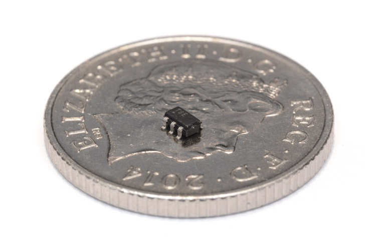
An entire computer, inside that little thing.
There are four in the series. The tiny4 and tiny5 have half the memory of the tiny9 and tiny10; the tiny4 and tiny9 have no ADC, whereas the tiny5 and tiny10 do.
Instead of the usual ISP method of programming, there's this Tiny Programming Interface (TPI) which uses only a single data line, along with the clock line and reset pin. To my delight, it turns out that avrdude and my USBASP programmer already support TPI, without me having to do anything. But before we can use it, we need a way of connecting it up.
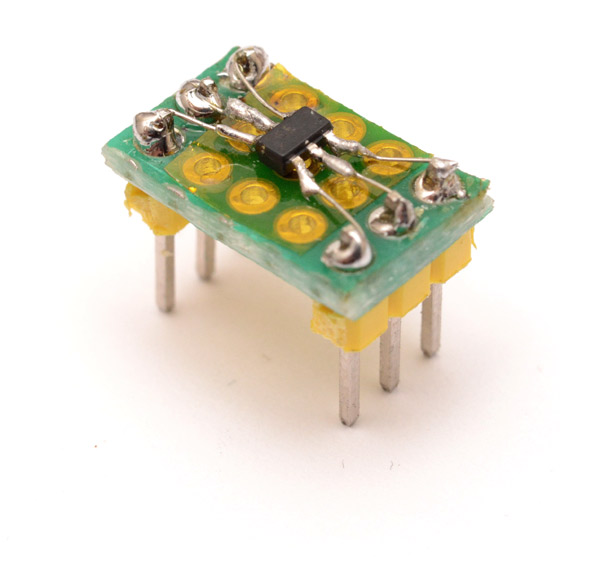
Not exactly my finest work, but it'll do. With the USBASP programmer, we just connect MOSI to the data line and leave the MISO floating.
MOSI -> TPIDATA
SCK  -> TPICLK
RST  -> RESET
It took me a few goes to realize that it will only program at 5V, not 3.3. It seems that avrdude tends to crash a lot, right after exiting, so there's probably some setting I've not configured, but reading and writing to the flash works fine, which is all we really care about.
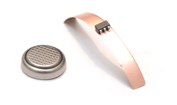
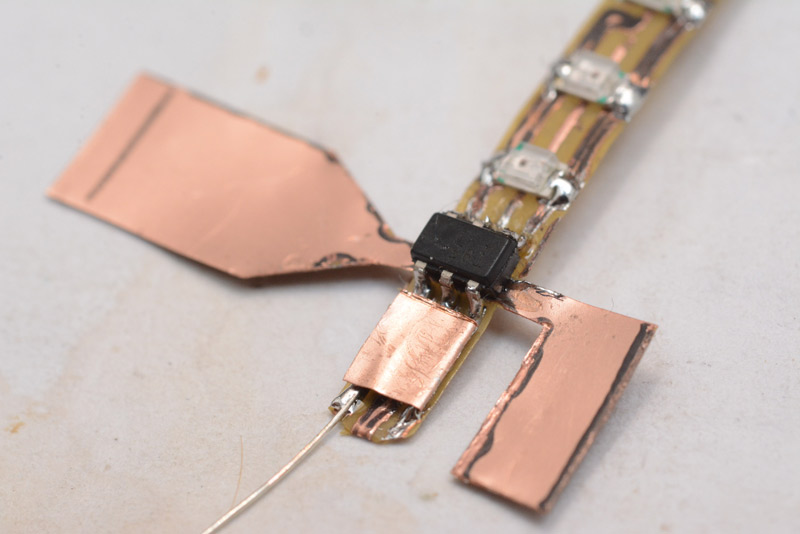
What I'd really like is a test clip, like I've got for the SOIC-8 chips and the DIP ones. These are fantastic, not only can you program a bare chip but you can even clip onto it after it's soldered into a circuit. The only things I could find were test sockets, which are generally expensive and difficult to get hold of. I tried to cook up my own concoction.
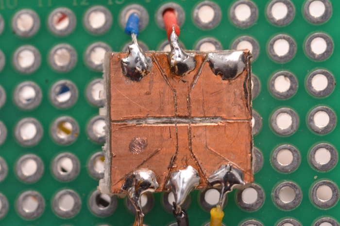
This is a bit of copper-clad board into which I carefully scraped some lines. The chip can then sit on it and be programmed with the ISP cable.
I tried to make a kind of clamp which would hold the chip steady, but it's really difficult to get the right amount of force. Too little, and it doesn't make contact. Too much, and the legs bend outwards and it loses contact entirely. The problem is that it's missing the all-important spring-loaded parts of a real chip holder. But, for a chip that's freshly pulled out of the tape, gentle finger pressure on top is enough to talk to it reliably in this way. I think the best thing to do is develop on the breadboard with the adapter, then load it onto a new chip when we're ready to solder.
The next question is, what to do with such a thing? It wasn't like we were pressed for space with the ATtiny85. I could make a smaller MIDI synthesizer, but I suspect people are getting tired of my matryoshka doll of ever-smaller synths.
So, brace yourselves for yet another stream-of-consciousness meandering project that struggles to justify itself beyond the baseline "I had some bits on my desk, and I stuck them together."
We have three I/O pins available. Maybe four, if we use the reset line. Flashing a few LEDs is the first thing that comes to mind. The classic way of controlling lots of LEDs from very few pins is called charlieplexing. It works by exploiting the properties of LEDs and the ability of microcontrollers to tri-state their pins.
I approached electronics from more of a software background, and when I first started I didn't really understand what a potential difference meant. Voltages are always relative, and our concept of "zero volts" is totally arbitrary. If I have one wire at +10V, and another at +15V, connecting a component between them will feel a potential difference of 5V. As simple as this sounds, many beginners feel uneasy unless they're connecting a part between an I/O pin and power or ground. Most microcontrollers are able to both source and sink current, so there's no reason not to connect up LEDs like this:
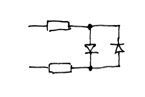
Imagine your chip is on the left with its pins connected to the resistors. Setting one pin high and the other low, current will flow in one direction and one LED will light up. Switching the logic states of the pins reverses the current, and the other LED will glow.
Charlieplexing extends this by setting certain pins as inputs, which 'disconnects' them from the circuit. So the classic charlie-plexed arrangement for driving six LEDs from three pins is:
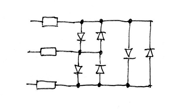
One pin is set to tristate, the next is high, and the third is low. The six permutations of those states will each light up just one LED. You'll notice that when an LED is lit, there are two others which feel the full voltage across them, but in series. This plays on the dynamics of LEDs. The voltage / current curve is exponential, so two diodes in series, when connected in parallel with one diode, will have half the voltage, and so feel almost no current. It's for this reason you can't improve the power capabilities of diodes by stacking them in parallel – unless they were perfectly matched, all of the current will end up going through just one of them.
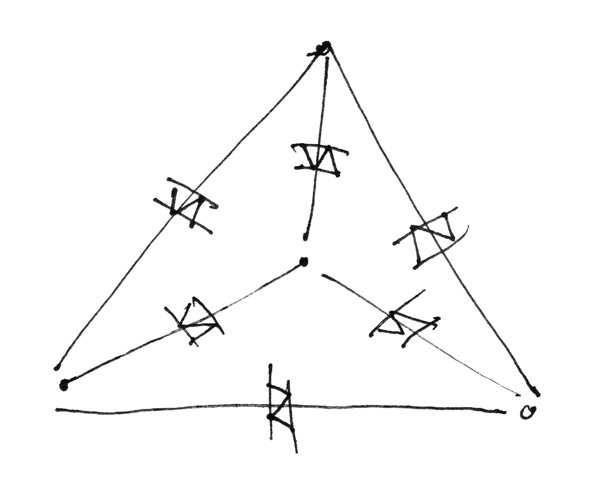
I was pondering about the charlieplexing circuit and I feel that the diagram above doesn't really convey the symmetry of the situation. It's basically a triangle, with pairs of opposing LEDs between each corner. But you always see it drawn like the diagram above. Perhaps it makes it easier to lay out on a circuit board. I was doodling about on some notepaper, and came up with this:
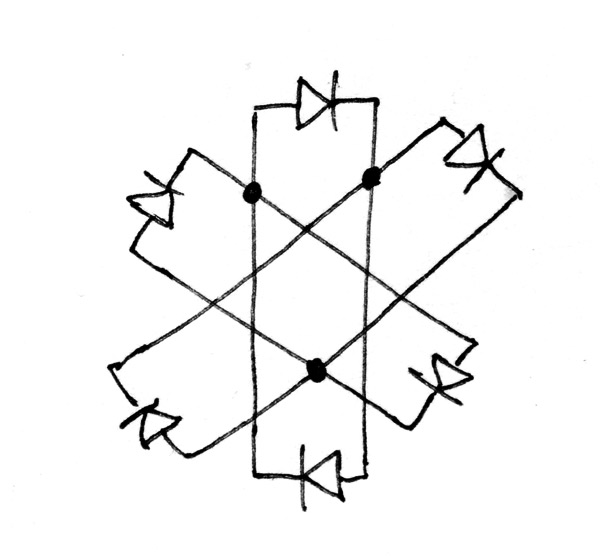
Well, I drew the LED pairs first, but it took an embarrassing amount of brainpower to figure out where the connections needed to go. The three joins are where the resistors would attach.
It's funny how difficult it can be to rearrange a circuit in your mind, even for something a simple as this. It reminds me of knots, and the mathematicians that study them. There are cases where two different knots, known for hundreds of years, are discovered to be identical only after expressing them in a special notation. People didn't notice, because mentally rearranging a knot is not easy.
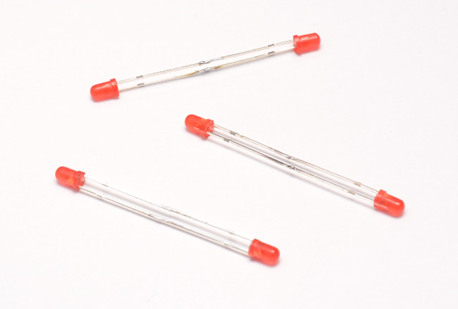
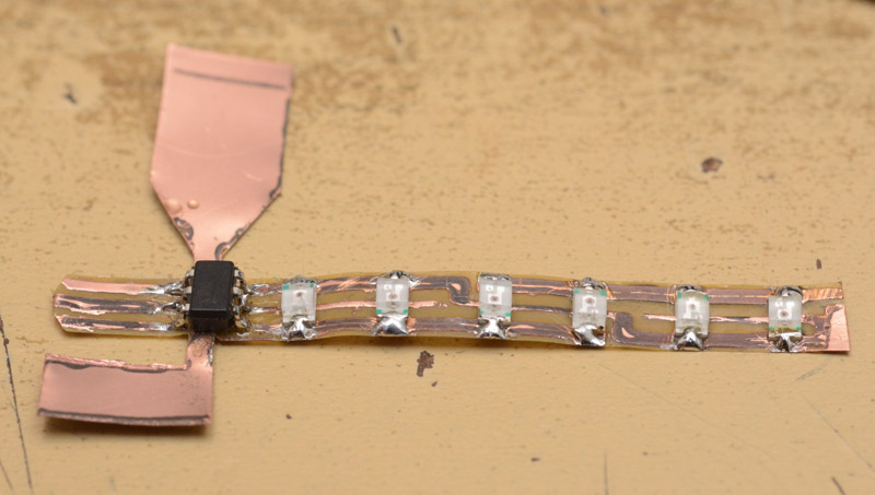
Anyhoo. To see if this worked I assembled it. Opposing pairs of LEDs first.
I soldered them end-to-end, which is a real test of soldering ability. You have to have a perfect join, fully wetted on both surfaces, and hopefully with no excess. The top one in this picture is not so good, the bottom one is real nice.
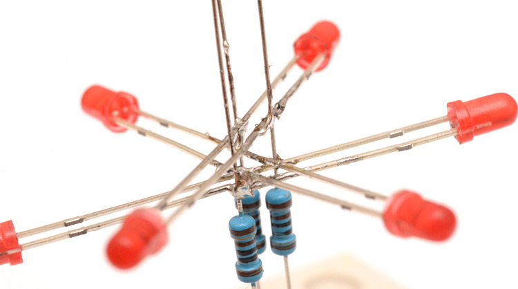
Next is the hard bit. There are situations where I think to myself, this could be made easier by doing X (building a hexagonal jig, for instance) but I refuse to do X because I've already invested time in to trying to do it the hard way (holding three things in one hand, for instance). Sticking the LEDs to the resistors, getting them centred and hexagonal, is one such situation. The result may look messy, but this was a serious test of dexterity.
To see if it works, we need to start programming the tiny chip.
The ATtiny9 has 32 bytes of RAM, which is a perfect amount really. Enough to have a functional stack, but small enough that the direct memory access instructions can be just 16-bit. This helps conserve our 1kB of program space. There are quite a few chunks of the AVR architecture that have been cut out, the lower sixteen registers have disappeared, and many of the instructions are gone.
A simple test of the LEDs doesn't require learning anything new though. We just need to call DDRB for data direction and PORTB for the high/low states, and lo-and-behold each of our six LEDs can be lit individually. Interestingly, the pullup resistors for input lines are controlled from an entirely separate register, which means it's possible to enable pullups and configure the output low, which would just constantly waste power. This register arrangement works to our advantage though, since we can know for sure that the pullups won't be on, and any pin can then be tristated in a single instruction on DDRB.
I made it cycle through the LEDs so it lights them one at a time. Better to have them PWM'd, though, in a smooth curve. Ordinarily I'd just stick a data table in there and load values from it one at a time to control the LED brightness. In this case, it seems there is no LPM instruction in the tiny9 architecture. According to the datasheet, the program memory has now been mapped to the same address space as the RAM but starting at 0x4000. I got a little excited that we might be able to access PM with all three pointers, but alas, it can only be read by the Z pointer.
To light all of the LEDs, we illuminate one for a moment, then illuminate the next for a moment, and so on as fast as possible so that to the human eye it appears as if all are illuminated. To dim their brightness, we just need to change the lengths of those moments. But we also need to add delays inbetween, equal to the time we shortened the moments by, so that the entire cycle is of constant speed. At the end of every cycle we can read from the data table, and update the brightnesses, so that it slowly goes through every value.
To generate the data table I just used my usual technique. Javascript console!
a="";for (i=0;i<256;i++) a+=","+Math.round(2+60*Math.pow((1+Math.sin(2*3.1415926535897*i/255)),2)); a
Numbers pulled mostly out of a hat, but that was a sine function, scaled from radians to 256ths of a circle, and squared to linearize the brightness. By making it step each LED through this table with an offset, we have a glowing ring of lights that chase each other. Easy.
I expect the reader would like a demonstration. I flashed the chip, then connected it to a single coin cell on this breadboard. (The coin cell is held between two header pins diagonally, a useful technique for an improvised battery holder.) A standalone charlieplexed star.
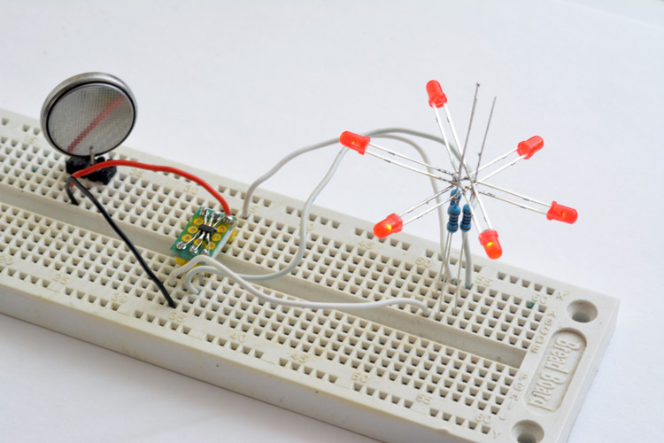
Click here for the animated version (.gif, 2.49MB)
To be honest the low framerate of that .gif doesn't do it justice. In reality, it's a silky smooth circling sensation.
Next up I figured I would program some more flashing routines. We need a way to cycle through different modes, and it occured to me to use the reset pin as a switch. The RAM isn't erased through a reset, so we can just write our current mode to a location, and on startup, increment it then jump to that bit of code.
An obvious mode for a tiny LED blinkenthing is to flash a message in morse code. We can do that. This requires multiple readings from program memory, the first to look up the current character in the message, the second to lookup what flashing pattern that character represents. There could be a really neat, dense way of representing the character set, but when you're storing the character set and its decoding mechanism in the same bit of memory, it pays to make the encoding a little less dense and a little easier to unpack. I went for a simple notation, using a single byte per pulse which would either represent a dot or a dash. The characters are different lengths, so the last byte in the character has an end-of-character flag. Each character is then padded with zeros to be four bytes, which means we can look up the character by subtracting 'a' and doing a double left shift.
Some characters have more than four pulses, but, well, I left them out for now. There's room to add them if we really wanted. Some care was needed to get the timing correct, a dot has to be one-third the length of a dash, the inter-pulse space has to be the length of a dot, the inter character space three dots, and the inter-word space seven dots. The wikipedia page is a pretty good reference for this.
Before long I had it flashing "the quick brown fox jumps over the lazy dog" on repeat. Neat. It's surprisingly hard to read visual morse code, I've only ever decoded it aurally and so I slowed the message down a fair bit. The way the data tables are arranged, the message could be 128 characters, but with some shuffling it could be made longer.
There was still a fair bit of room left in our cosy 1kB of flash, so I made another mode. I wanted a pseudo-random number generator, I've implemented them in assembly before but this time our architecture is different. Certainly no multiply instructions available. But the simplest RNG is a linear feedback shift register, and shifting is easy. In fact I just copied the logic for a 25 bit LFSR from this app-note from maxim. Their processor can only shift on the accumulator, whereas in AVR the shift operation works on all registers, so our code ends up a fair bit shorter.
At first I made it light up random combinations of LEDs, but it didn't look nearly as interesting as I was hoping. I wanted a chaotic sparkle effect, like the shadows thrown around a campfire. I combined some of the same PWM logic into it, and gave each LED a fade-away routine. The generator sets some of the LEDs on, then they fade away to nothing. This still didn't look that great until I made it randomize the timings too, then it actually felt a bit more random. There are supposedly 30 million iterations before the cycle repeats, and we're calling the function less than ten times a second, so the pattern will certainly outlast any battery we give it.
I may think of more modes, but one that we definitely need is 'off'. Reducing the number of switches is certainly a way of reducing physical size. Most LED trinkets are disabled only by pulling the battery, which doesn't appeal to me. The ATtiny9 has a decent sleep mode, so I set one mode to just turn off everything and power-down sleep. The reset pin will wake it up again, just as before. Pretty convenient really. I measured the power draw while off, and it was below the resolution of any of my multimeters, 0.1μA. Or in other words, 10,000 hours (over a year) to drain 1mAh of charge. Given that most batteries will self-discharge within a few years, and even the smallest coin-cells hold many tens of mAh, this power-down state is easily good enough to never worry about.
I have stuck the source code up on github, because that is where all the cool kids stick their source code these days.
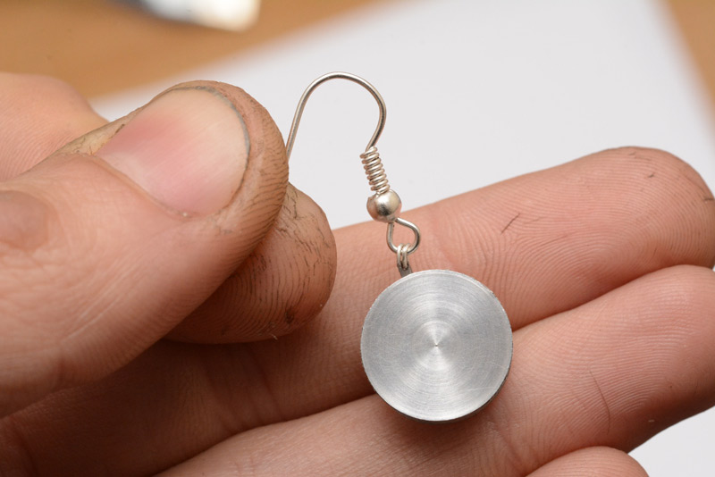
So the code was ready, but now my through-mount LED charliestar was looking rather unwieldy compared to what could be. At this point, I was leaning towards something challenging, something suave, something wearable. And that pretty much narrows us down to either cufflinks or earrings. But first, an interlude.
Interlude
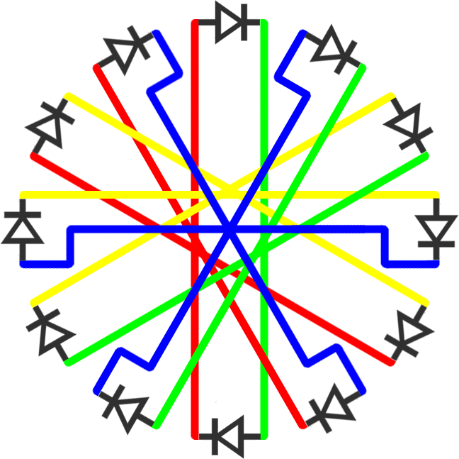
For the challenge, I tried to lay out the star circuit as it would be for 12 LEDs – four pin charlieplexing. Six LED pairs overlaid like the hours of a clock. Drawing it out, like the little doodle above but with twice the LEDs, it isn't at all clear where the joints need to be. After struggling with this for a few minutes, I eventually turned to photoshop for the solution. Since any given leg of any given LED will be connected to one of the four pins, we can colour-code every wire as to where it's to be connected. Then, it's just a matter of rotating and permutating the different LED positions until the similar colours all overlap in the fewest joints. This was my solution:
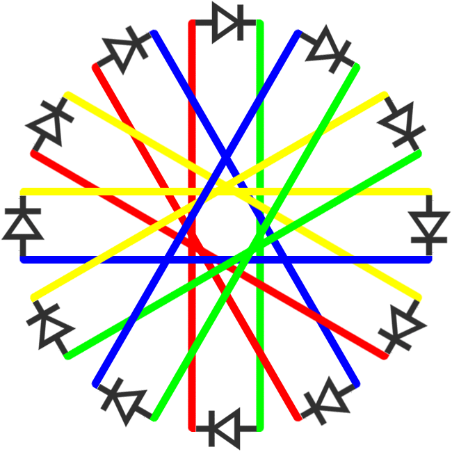
Obviously it's not ideal since it's six joints instead of four, but with this sort of thing it isn't clear if there even is a perfect solution. I suppose before we had three pairs of LEDs, and three pins to connect to, now we have six pairs of LEDs and four pins to connect to. Does that mean that six joints is the minimum? I feel like if I stare at it long enough, a better arrangement will suddenly jump out at me. Or maybe I'm just going nuts. Given the difficulty of assembling the three-pin version, it's unlikely I'll ever be building this, but it's an interesting puzzle nonetheless.
Later: there is a better arrangement. I'll stick it at the end of this page, to give the reader a chance to think about it.
Part two
In which the author fashions a pair of utterly tasteless LED earrings
I ordered a pack of CR927 lithium batteries, and continued to ponder. Coin-cell batteries that start with 'CR' are named after their dimensions, the ubiquitous CR2032 is 20mm by 3.2mm, and so this CR927 battery is just 9mm by 2.7mm, the smallest of the commonly available types. There are smaller batteries, the zinc-air ones used in hearing aids, but these all output less than 1.5V, so it's not possible to light an LED with them without stacking multiple cells, or making a boost converter, which probably consumes even more physical volume.
We'll switch to surface mount LEDs, I've got a pack of a few hundred in my drawer. I was thinking about how to solder it all together in the tightest possible package, and ditched my first idea for something much better, something far more similar to what is done in industry when the conditions get cramped. A flexible PCB!
I've never made a flexible PCB before, but the raw material they're built from (copper-clad polyimide) is available, and sold under the trade name Pyralux. The process of etching it is identical to etching copper-clad FR4, except this time the backing is polyimide, also known as Kapton.
Yes, the concepts were melding together in my head as I waited for delivery. A ring of LEDs, wrapped around the tiniest of batteries, a self-contained glowy thing.
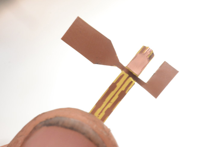
A few days later, my ingredients had arrived. This time I'm using the ATtiny for scale!
The pyralux is very thin material, only barely stiffer than aluminium foil. The kapton does give it a bit of springiness though. The strip in the picture was cut to size that it would wrap around the circumference of the battery perfectly, so, we need to design our PCB to fit into that footprint. The width is 3mm, the length is about 30mm.
We wrap the circuit around the battery, that much is understood. We space the LEDs evenly, although there'll have to be a gap where the chip is, along with the resistors. What really troubles me is the switch. I'm thinking that a tiny push switch could be incorporated into the perimeter, but the smallest tactile switch that's easily available is over 3mm across. There are extra small tactile switches, seriously minute ones, but only from real distributors instead of ebay, which means a £12 postage charge for a 20p part. Ugh. The switch is, by far, the hardest element of this design.
The surface mount LEDs I own are 0805, which are of course 0.08 inches long – just over 2mm. For flexibility, and to conserve lengthwise space, we need to mount these perpendicular to the length of the pyralux strip. With solder, that means the LED covers the full width of the board. A single trace under an LED is doable, but two traces isn't going to happen. And we need to wire up all six LEDs on a single side. You know what this means? More permutations of the charlieplex knot.
My design at this point still had current-limiting resistors, but in fact the coin cell battery will play to our favour here. Coin cells have very small surface area on their electrodes compared to other batteries, so they can't actually deliver much current. In effect, we can use the battery's relatively high internal resistance as the current limiter, and avoid the need for external resistors entirely. It's possible this will de-linearise the brightness a bit, since dimming the LEDs means less current draw and the battery voltage will increase. But some testing showed that to my casually observing eyes, there was no difference. Missing out these resistors frees up a huge amount of space (the difference between 7 components and 10).
Hmm...
Knot permutations and switch complications,
Mental rearrangements of component placements,
Pyralux bent into LED rings,
These are a few of my favourite things.
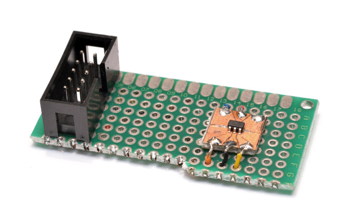
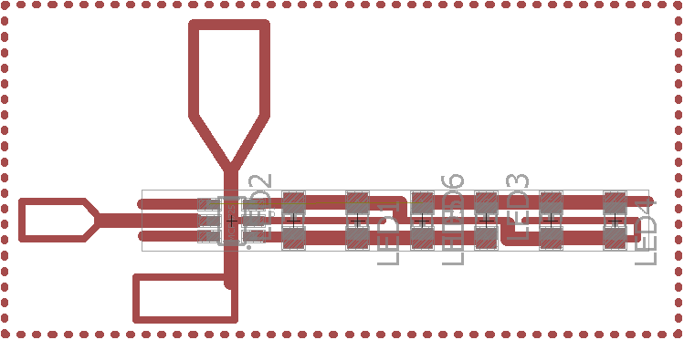
The eagle design:
And the exported .bmp for laser etching:
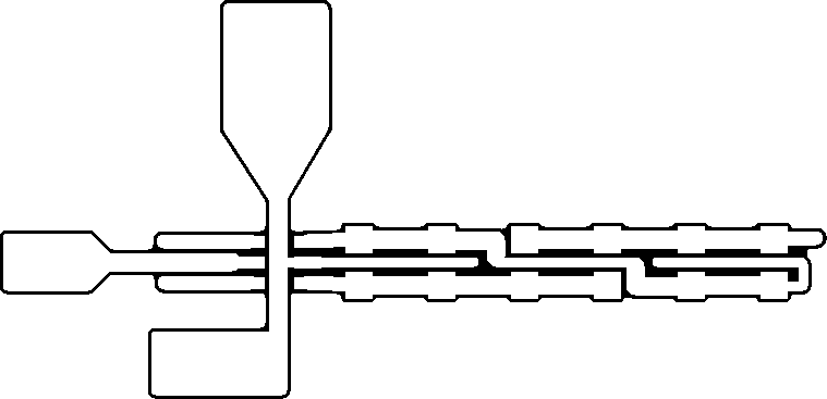
The design was set. You'll notice there's still an air-wire in the eagle screenshot, because for this, we had to think in 3D. The only way to arrange the circuit was for a jump from one end of the loop to the other. The switch, well, we'll explain that in a moment, if it works.
To etch, we first spray-paint the pyralux and then stick it into the laser cutter.
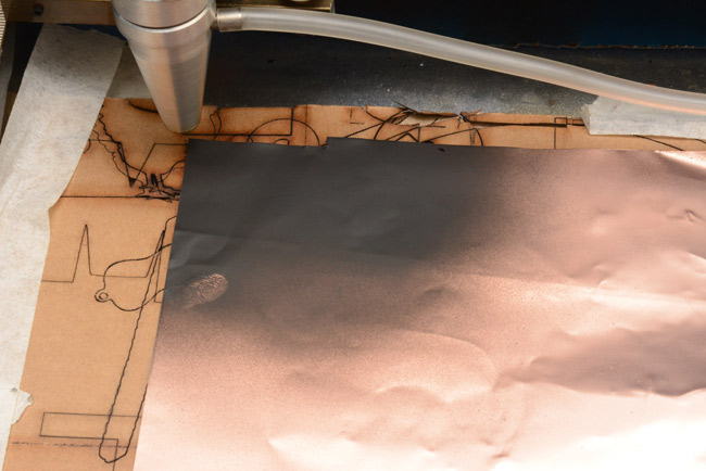
The thumbprint was me impatiently checking if the paint was dry yet.
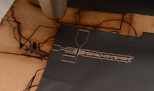
I didn't line it up with the edge all that well, but the tab sizes were chosen arbitrarily anyway. The middle wires came out a bit thin, but apart from the centre one, these were only intended as infill. The less copper you have to etch, the faster the etching takes place.
To etch, I used my normal technique, dabbing the smallest possible amount of acid onto it with a sponge. This keeps the bottle at full strength, and the used acid is wiped up with a piece of kitchen towel that can then go into an ordinary bin, which is probably much better than down the drain.
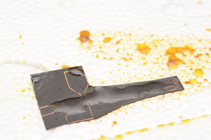
I'm doing this on a polystyrene tray, but it seems that most non-metallic materials are immune to the acid. After about 15 minutes the etching has done most of its work. Since the base material is transparent, we can easily check progress by silhouetting it against the light.
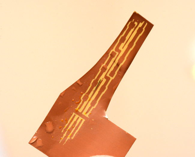
This is the underside of course. You can see that the paint mask for one of the spindly wires has come loose, I must have dislodged it with the sponge, but towards the end of the etch since the main copper is in the right place. I didn't bother waiting for the tabs to etch, we're cutting their outlines with scissors and a razor blade in a moment anyway.
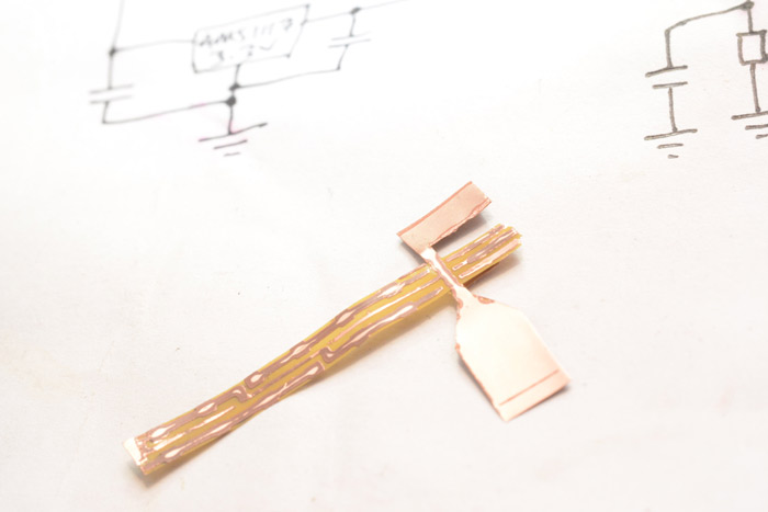
The paint was removed with IPA, then the outlines traced and a couple of remaining bits of copper were carefully scraped away. The first tab folded over, this one is for the positive battery terminal, around the rim of the coin cell.
Eww fingernail. The other two tabs have to be left hanging until the parts are in place. I feel like one clumsy move could rip them off.
The acid seems to have worked its way under the mask a little, leaving a discoloured section of the remaining copper. This will have to be scraped off before we try and solder to it. We're bending this circuit board; every joint has to be perfect.
Eh... perfect enough... did I mention this thing is really bloody tiny? I don't have a reflow oven, but even if I did I'd be worried that the pyralux doesn't stay flat, it took a fair bit of work to keep it as level as that in the picture. Maybe if it were assembled before cutting out. Maybe next time. We can't even properly test it, until the ring is completed. Before we can do that, we need to assemble this tiny tactile switch. I tinned the end of a bit of scrap pyralux, then soldered it face down to the reset line.
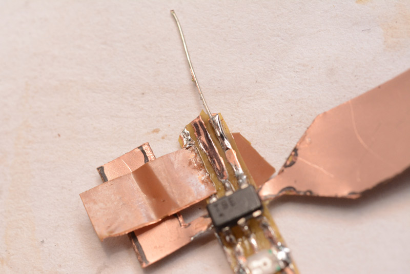
I also added a wire, ready to make the jump. The reset pad is now folded over and trimmed to length.
Hopefully it's now visible how the switch will work. The L-pad gets folded over the top of the chip, and pressing down will make contact with the other pad. I'm counting on the kapton's elasticity to give it an acceptable number of actuation cycles.
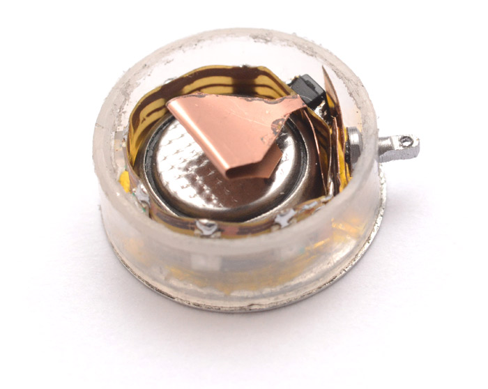
The join comes next, and this bit is probably the hardest of all. Perhaps a jig would help here. I don't know. The springiness! After a number of attempts, it finally reached an acceptable connection. At last, we can insert it over the battery, and see if it works.
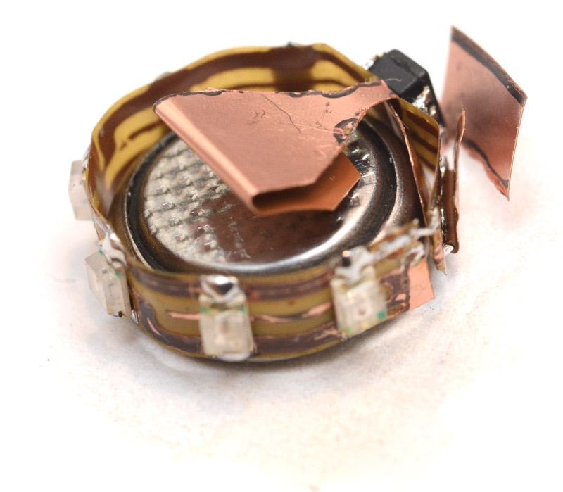
Oh man, this is getting exciting.
I gently tap the switch, and...
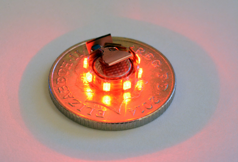
Huzza! Not only do all the LEDs light up, but they do so in the correct order! I was actually really concerned about that, since the order is different from the hexagon star above. I'd altered the code to pulse them in the theoretically correct order, but couldn't test until now. Of course, if it were wrong, we would have to desolder the chip to reprogram it (or more likely, toss it and program a new chip, it's more than 32p of my time to clean up the solder-drenched legs).
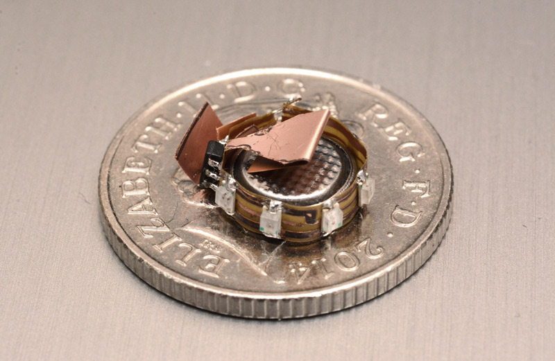
Right. Next up on the agenda is encapsulation. Earrings are intended to be delicate, but calling the above delicate is a bit of an understatement. A cylindrical case of the smallest possible form-factor is essential.
The circuit is just over three millimetres thick, it could potentially be trimmed a little. The diameter, I might have to adjust the switch a bit, but it's able to freely rotate within the jaws of the calipers at 12mm.
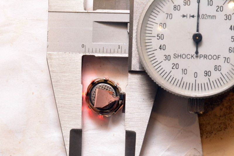
Pictured at its biggest diameter. Obviously the case needs to be transparent around the rim. First idea: laser cut acrylic. I have clear acrylic in thicknesses of 2mm and 5mm, so I cut out a few rings of each.
The problem with laser cutting is that the edge isn't perfectly straight, it's tapered. On most length-scales this isn't an issue but here it actually dominates the shape of the ring. Laser-cut acrylic generally has a beautifully clean edge, but for very small shapes the whole part starts to melt. One technique for equalizing the taper is to stack two cutouts on top of each other, which works very well for equalizing the taper on things like gears.
We need a 4mm thick ring, so I figured to perhaps stack two 2mm rings opposingly. But the 2mm rings kept coming out like this:
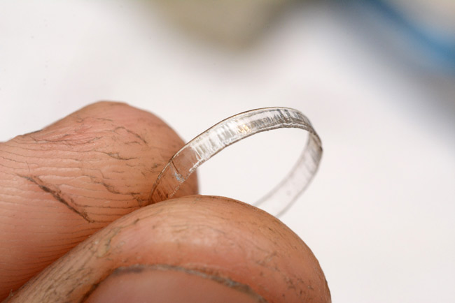
Stacking after cutting just wasn't going to happen, both the top and bottom are so melted that there's virtually no surface area for the superglue. I tried increasing the wall thickness but even at 1mm it was hopeless. So, I tried cutting the 5mm stuff and sanding it down.
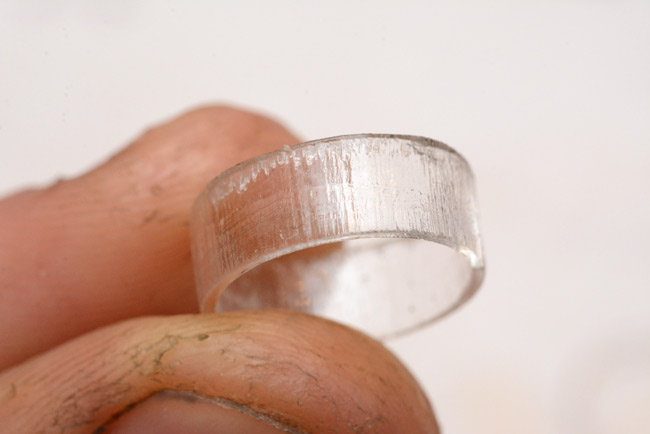
I was hoping that I could sand away the worst of the melted edge, but there's still a big disparity in diameter and wall thickness from one edge of the ring to the other. The vertical lines on the ring are artefacts of the low resolution of the laser cutter, the stepper motors are moving in discrete steps. It would be best to cut a ring with very thick wall thickness, then machine both inside and outside surfaces on the lathe. With enough sanding we could get a uniform surface, transparent and perfectly round. It may even be possible to lightly touch the surfaces with a blow-torch after machining, which would re-melt them and the surface tension would pull it to a nicely smooth surface. But, how do we hold the ring on the lathe? Acrylic is actually not very strong, it can be quite brittle, and several of my attempts cracked.
After about ten ring attempts, I decided to switch direction. I have some borosilicate test tubes, but these are all 15mm diameter, which is just too big. It's possible to reduce their diameter with a blowtorch on the lathe, in fact, stretching a glass tube is one of the easiest glassblowing techniques to do. But I don't have a kiln, and I learnt the hard way that you absolutely have to anneal the glass after working it, or it becomes shatteringly brittle. By anneal, I mean cool it down over the course of an entire day. Another concern with a glass ring is how we're going to attach the end-caps. These have to hold put, but be removable to change the battery. I don't really see a way of attaching them to glass that's removable and durable.
I was rummaging for something that would fit this bill, and finally remembered that I have a complete set of different sized hypodermic syringes. For totally legitimate reasons! These are super useful to have, there is no cheaper source of finely manufactured tiny metal tubes. It just so happened that one of these had an outside diameter of 13.7mm, which is just a smidge larger than what I was hoping to create with the laser cutter. I pulled it apart, cut the top off and measured its inside diameter too – 12.4mm.
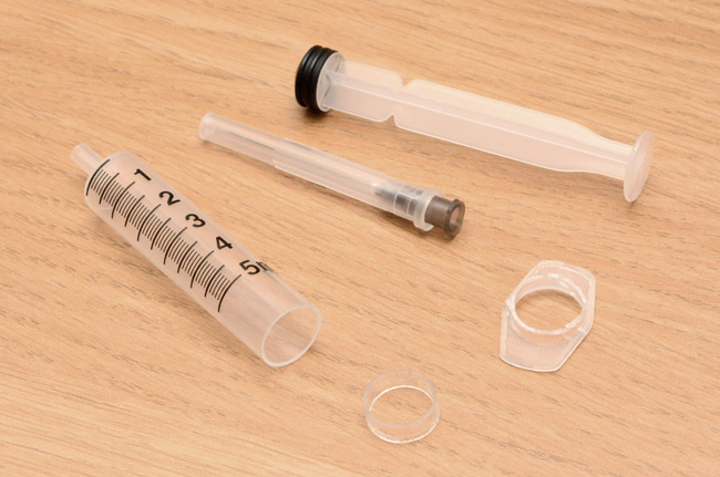
I put one of my acrylic attempts in that picture for a sense of scale. It's so close in diameter that it's about as good as we could have hoped for. The only issue is the slightly opaque nature of the plastic, I would have preferred something glittery. For an initial prototype however, this is perfect. It's also a very strong plastic, absolutely no chance of fracturing or shattering.
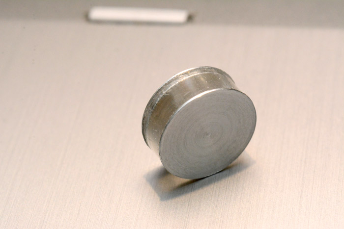
There's no way I can cut a thread into it, though. The end caps will have to be press-fit. I used the lathe to cut off a 4mm ring of the plastic, then removed the burrs very carefully with a stanley knife. Next I turned a bit of aluminium down to diameter and using my smallest partoff tool, cut a groove about 0.5mm from the end. This smaller diameter I cut to 12.5mm, so it should snap into the plastic ring firmly.

Then I shifted over another 0.5mm, and parted off.
I may have been a little ambitious at 12.5mm, since it didn't immediately fit into the plastic ring at all. However there were some burrs left after parting, and a bit of filing later, it was possible to snap the disk into the plastic firmly.
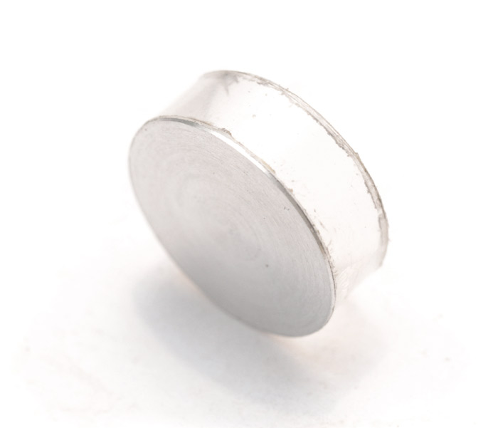
I tried dropping this onto the desk from a height a few times, and it didn't jump out, so that's about perfect really. I covered the inside surface with kapton to avoid shorts, then set about manufacturing another. You can just make out the yellow tint of kapton on the inside.
And finally, the fiddliest bit of all, the switch. For this I used my staple printer-sourced free-machining stainless steel, turned down to 1.5mm, tidied up with a needle file then freehand crossdrilled 0.5mm. I could really do with a cross-drilling jig. The result is not quite on-centre.
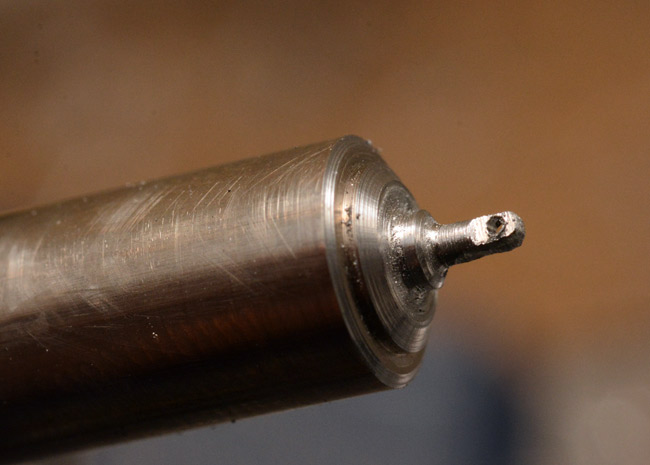
I parted it off leaving a flared base to keep it captive in the earring, then drilled a 1.6mm hole in the plastic case in which to insert it. Some final tweezer-work and we're on the home straight.
I was a little concerned, perhaps unnecessarily, about the switch pressing itself when the earring is handled. I added a tiny square of kapton onto one contact so that only half of the pad is exposed, increasing the required force to activate it.
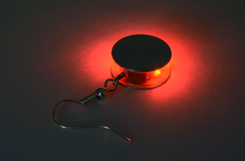
With a satisfying snap, I pressed on the other side of the case and tapped the switch.

Splendiferous! Fantabulistic. I honestly wasn't expecting it to work all that well, but it cycles through the modes perfectly. There is a notable lack of a 'click' to the switch action, more of a squish motion when you press it, but it operates perfectly. The travel is very short as you'd expect.
To turn it into an earring, I had already ordered some commercially made ear hooks. These are silver plated and come in bag of over a hundred, but many of them are mis-manufactured. I found a nice looking one, and discovered that the wire thickness is 0.7mm, far too large for my 0.5mm hole. Remaking the switch, or buying new hooks, were both out of the question. There's a spring around each earhook made of a similar silver wire, but thinner – just thin enough to fit through my switch stem. I sacrificed one of the hooks to salvage its spring and fashion a coupling ring. Aha, an earring!
This coupling certainly makes it a lot more dangly, but also makes pressing the switch a little less convenient than I'd imagined since you can't directly press on the hook. Still, being dangly is probably worth it.
I will admit, I'm pretty pleased with that.
But of course. We can't just make one earring. We have to make a pair. So! Time to repeat the process. This time I'll attempt to film it.
Building another (video)
Indeed, I agree, there's no question that it's absolutely obligatory we do some vanity shots on the laptop keyboard.

Magnificent, marvellous, and other hyperbolic adjectives.

Box
Just in case there was any ambiguity in the matter, let me take a moment to clarify that your humble author will not be the wearer of these new earrings. They are, in fact, a gift.A gift requires a box. In many cases the box is the best bit. In this case, the box will be a moderately conventional cardboard construction. With the earrings finished I wanted the box out of the way as quick as possible, and tried my best to source suitable materials from my immediate vicinity.
I found some carbon black anti-static foam which would make a great lining, but there wasn't enough of it in a single piece. The lining needs to be black, or at least darkly coloured, but after fruitlessly searching for a material that ticked all the boxes, I changed direction. I have some microfibre lens-cleaning cloths which are very soft to the touch, but they are all bright pale green. I soaked one in black dye which worked fine, but after drying, the fabric had lost all of its softness. This is really on the periphery of my experience, so, lacking any better ideas I repeatedly crumpled, washed and ironed it until the stiffening was somewhat reversed. The black cloth was then wrapped around some foam padding to make the lining.
There's a certain type of very thick card which, when wrapped in satin-black paper, exudes "luxury item". I was going to laser-cut the box but ended up doing it all with a craft knife since for the paper-wrapping stage it would be compulsory regardless. Few pictures were taken, but the procedure involves cutting rectangles of the thick card of the right proportions, taping them together in the basic shape, then gluing the wrapping paper all over, being especially careful not to get glue on the outside surfaces. The wrapping paper was sourced from another 'luxury' box, the packaging for an old smartphone. Peeling it off was laborious but likely quicker than venturing out to an actual shop.
The semicircular cutouts were traced around a 1p coin. The exposed card was darkened with a Sharpie permanent marker. I made one small mistake with the lining, when gluing it into the lid I pressed down too hard and the foam sucked up some of the glue, which solidified part of it. Luckily I'd made the foam in the lid double thickness anyway, since I wanted the earrings to be clamped between the padding when the box is closed.

The lid looked a little plain, and perhaps it would have been best to leave it like that, minimalism and such. But the creative urge doesn't just grind to a halt, it peters out over a period of time, sometimes to our own detriment. So I ended up laser-etching an emblem onto the lid, a stylized schematic of the charlieplexing star.

I moved the wire joints compared to the earlier version, an alternative but still valid circuit, I figured it would be more pleasing to have them all on the inner hexagon, although the way it etched they are hardly visible anyway.
Right, that's really it, I'm going to stop now.
Solution to the twelve-LED charliestar puzzle
Going back to basics, if you quickly draw out the four-pin charlieplexing arrangement:

That's my invented symbol for a pair of opposing LEDs. The act of drawing this drives home the fact that every pin has one pair of opposing LEDs to every other pin. And of course, in 2D with the pins at the outside, that means there has to be a jump. But! What if one of the pins were on the inside?
Aha!
So it seems all we need to do to build a 12-LED charliestar is put one of the joints on the inside, at the centre. Not particularly beautiful, but here we go:
Fantastic, great, wonderful, sublime yes. Maybe I'll build it some time. Now, how about a 5-pin, 20-LED star?