
Games Console
22 Dec 2018Progress: Complete
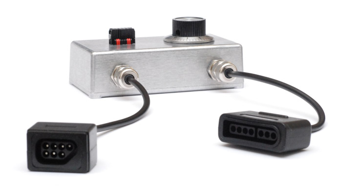
Behold. A games console!
This is a project from years ago – it was my first "serious" electronics project.
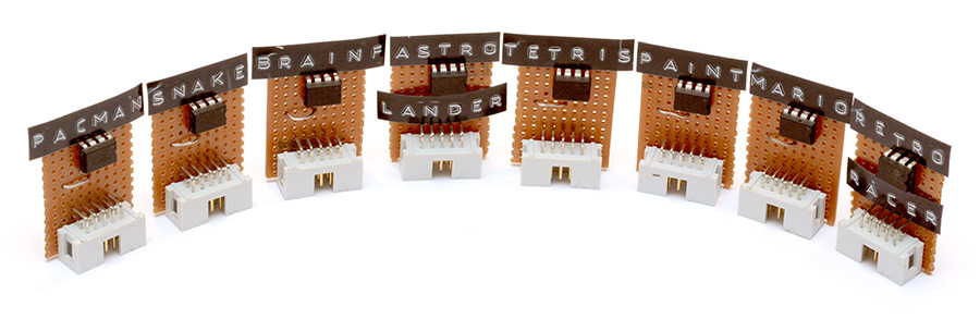
A fun and popular coming-of-age project for microcontrollers is to make a game that plays on an oscilloscope. Partly because I couldn't decide which game to make, and partly because I wanted to make something special, I decided to build a games console, with a handful of different games on little cartridges. I built the prototype and wrote all of the games in 2014 over a period of about two months. At some point in 2015 I went back and built the neat little enclosure for it.
I've started and stopped trying to write up this project page several times, so I apologise if the narrative is a bit jumpy. Some of it was written back then, some of it about a year later, some of it now. The problem is that the project was enormous. The final source code is over 12,000 lines of hand-crafted assembly along with about 100kB of constants data.
In addition to the low-level coding, I also produced playable javascript prototypes of most of the stuff. I'll put some of these demos up in the relevant places.
Contents
Because this writeup is so long, I have split it into multiple pages:
- Intro, the design and the bootloader (this page)
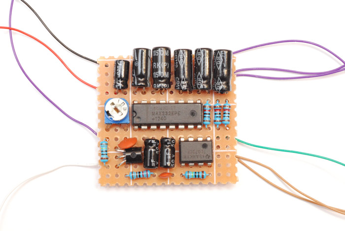
- The Circuit (written in 2015)
- Enclosure (written in 2015)
- Assemblage (written in 2015)
- Text and Brainfuck
- Music, Trig Tables and Anaconda
- Impulse Collisions and Retroracer (includes JS demo)
- Lines, Scaling and Astrolander
- Tetris and 3D transforms (with cop-out JS demo)
- Pacman (includes JS demo)
- Mario (includes JS demo)
Intro
Here are some answers to common questions.
How does drawing on an oscilloscope work?
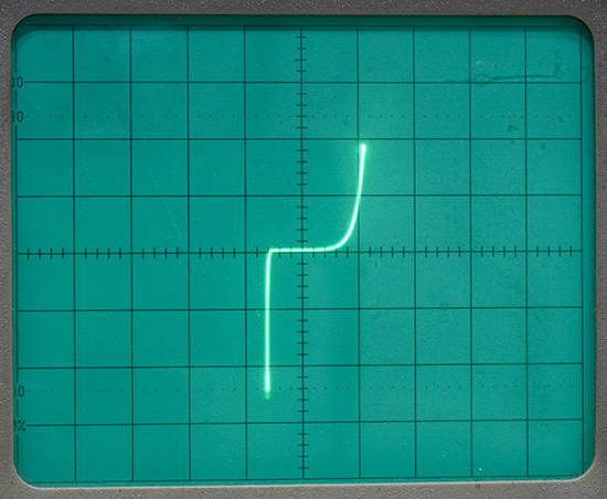
A CRT oscilloscope has an electron beam that strikes a phosphor to produce light, just like old televisions.Normally an oscilloscope scans the beam left-to-right at a speed governed by the time-base. In X-Y mode, the time-base is disabled and one channel controls the X position, the other controls the Y position. This is useful for plotting Lissajous figures, or even directly plotting IV curves. But it can also be used for funky music visualizations, or indeed, making vector graphic video games.
My oscilloscope also has a Z input, sometimes called a blanking input, on the back. With this, we could potentially render a complete bitmap to the display. But there's another, easier way to modulate brightness. The longer we hold the beam in one place, the brighter the spot will become. So a complete range of brightnesses can be had by just changing the dwell time.
Note: this only really works on old oscilloscopes. I've tried plugging the console into modern scopes which emulate X-Y mode, but it butchers the image. They're just not designed for rendering a video output like this.
How do cartridges work?
ROM carts, the type that almost all video games had, were plugged directly into a computer's address bus. In most cases they had some kind of memory controller chip in order to extend how much you could store on them, but still it ultimately plugged straight into the main circuit and the processor could read code and data straight from it.The Harvard architecture (as opposed to the more popular Von Neumann architecture) has the code in a separate location to the working memory. This doesn't preclude the use of ROM carts for the code, but the particular implementation of a Harvard architecture used by AVR chips (such as the ATmega used in this project) has a further restriction: the code must reside on the internal flash memory, and there's nothing you can do about it. In order to use game cartridges, I had to write a bootloader which reads the cartridges entirely, and overwrites the flash memory with their contents, then jumps to that code section to run the game. And to maintain the illusion, it detects when the cart is pulled out, and ends the game.
I didn't make a proper loading screen, but the beam X position is set to the flash address as it's being written. Before most of the games run, you can see the dot move horizontally as it loads the game.
How do you read out the Nintendo controllers?
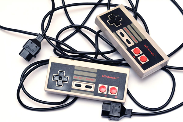
It's unexpectedly easy. Inside the controller, there's a shift register. You send it a latch (enable) and a clock signal, and it spits out a byte of data that's exactly the state of the buttons and D-pad at the time the latch was set. The SNES pad has exactly the same system, but this time it's two bytes, the second byte containing more button data.
Since this is just a shift register, I was able to plug it straight into the SPI port of the ATmega chip. For the two player games, I ended up bit-banging the communication to both controllers, reading them both out in parallel. SPI is very easy to bit-bang like this, because we're in control of the master clock signal, so we don't need to worry about timing at all. Even if the speeds vary widely, it'll still work. Also, you don't even need to read out the second byte with the SNES pad, simply stopping and latching again will work.
How about the sound, then?
This is done using the hardware timers of the ATmega chip. They're configured in waveform generation mode, which is a pleasing side-effect of the different PWM modes. Basically by setting particular PWM configuration bits, you can get it to vary just the frequency instead of the duty cycle. From the datasheets I sometimes get the feeling this was more of an accident that they turned into a feature, but I'm not complaining.This was all before I got into the MIDI ATtiny stuff that I did later, but this is where my interest in all of that started off.
The noise channel is done by amplifying the genuine noise produced by a reverse-biased transistor. This takes a fair voltage to get working, you need at least 12 volts for it to work really, and all in all the whole thing would have been simpler and no less noisy if I had just used a pseudo-RNG in software.
About the video
I should clarify this. In the video I said I started this project knowing almost nothing about electronics. It's not entirely true. But it was during this project I learned possibly the most valuable lesson of all:Electronics is LEGO. All the bits are available and all you need to do is stick them together. And the instructions for sticking these parts together are available in the datasheets.
That paragraph... it sounds so obvious, but if somebody had told me that earlier in life, I could have been so much further ahead by now.
Also, about programming in assembly. I'd done a teeny bit of x86 but always struggled with the bit I wasn't interested in: interfacing to the operating system. With bare-metal assembly, it's a different story. All of a sudden it's possible to concentrate just on the fun bit. Also, in the case of AVR, there are loads of resources available, not just the AVRfreaks forum, but the datasheets have code examples in assembly too. Unlike almost all other platforms, the manufacturer expects, even encourages people to program in ASM.
Two further comments about the video. I said it's sat on my shelf for four and a half years but the enclosure was only built in 2015. This is partly because I had realistic expectations about the delay between filming the video and actually posting it. Secondly, a glitch occurs in the pacman footage. I didn't notice it when I was filming, only after watching it back. It would be dishonest to re-film it. It's probably something simple but I have no intention of trying to fix it at this point.
Lastly, grammatically speaking, should I have said "these data" instead of "this data" ?
Design
Here is a beautiful retro diagram of the system architecture.
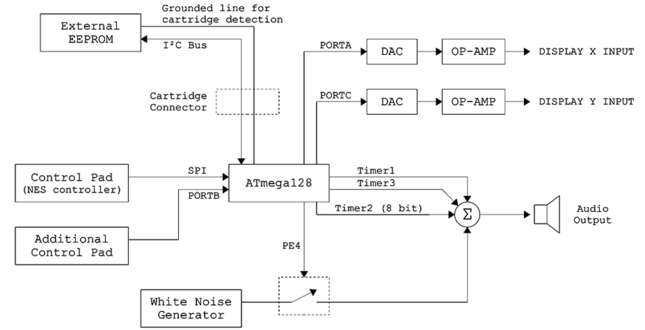
The ATmega128 has 128kB of flash memory. Simple (single address) I2C EEPROM chips have 64kB of memory, so when a cartridge is read by the bootloader it can overwrite the first whole half of the flash memory without worrying. The BIOS, the permanent code, sits in the upper half of the ATmega's memory. In fact, it's small enough to sit in the last few pages as a bootloader.
You may be familiar with Arduino and the concept of a bootloader to update the code on a microcontroller. In that case, it's used for development and firmware updates. In this case, it forms an active part of the end result and is used every single time a game is plugged in. Also, some of the shared code between games is stored here, which is why it can be thought of as a BIOS.
There is only one interrupt used in the whole system, that's the pin-change interrupt for cartridges being removed. It's possible to shift the interrupt vectors to the bootloader section, which is what I did, but then instead of a vector table it just immediately disables interrupts and clears the flag. So, whenever a cart is pulled out, the program counter jumps to the bootloader section, and doesn't jump back until the next game is loaded.
You might think that erasing and re-programming the flash memory every time a game is plugged in will wear out the memory. You'd be right. But it's rated for 10,000 cycles, so that's still quite a lot of gameplay I think.
I regret putting any shared functions at all in the bootloader. The problem is that I developed the bootloader in parallel to the games, and whenever I changed the bootloader it meant all of the game cartridges stopped working until I reprogrammed them, because the addresses for the functions they were calling had changed. As it happens, all of the games were much smaller than the 64kB limit on the cartridge size, so I could have quite easily copied and pasted all the functions into all of them.
If I really needed to have shared code in the bios, the right thing to do would have been to set up my own vector table, a series of jumps to functions within the bootloader section, placed at fixed addresses at the start. Then, the games can call the vector address, and when we change the bootloader, those jumps might change where they're pointing but the code would still work.
An annoying thing about having code or data in the bootloader is the addressing. A 16-bit address space can access 65,536 addresses (216). If those addresses are byte-sized, then you've got 64kB. AVR opcodes are all at least 16 bits, so they made the program counter a word address, so even though it's only 16 bit, it's able to address up to 128kB. Very efficient. But the problem is when we start storing arbitrary data in memory, and we want to read it out a byte at a time. In this case, a 16-bit pointer can only reach the first half of flash memory. The workaround is to add a 17th bit to the equation, a separate register called RAMPZ that lets you read bytewise data from the second half of flash. So it's possible to store common data, like font tables and so on, in the bootloader section, but in practice it's a pain to read it and again a better idea is to just duplicate it between cartridges.
I did implement the highscore table routines in the bootloader, mostly to reuse the I2C functions. The very last page of each cartridge is reserved for the highscore data. I used the hardware I2C controller on the ATmega which Atmel calls TWI for copyright reasons.
Because a lot of the constants and labels in the bootloader need to be accessed by the games, each game's source code ends with an include directive to import the bootloader. The development process meant re-flashing the bootloader every time. I re-wrote the entirety of the flash memory using the ISP connection. Some hidden development modes can be accessed from the "insert cart" screen. First, we can bypass the cartridge routines to run the game in flash memory at the moment. Secondly we can reverse the loading processes: when given this command, the bootloader reads out the first half of flash memory and writes it to the currently connected cartridge.
With those two functions it's possible to develop games without a cartridge, and to flash and re-flash cartridges when needed through the same system.
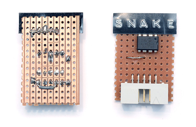
There are more details to the bootloader, but if you want to learn about them, you'll have to dig into the source code below. Alternatively, you can jump ahead to the next section which has some juicy soldering pictures.
### Bootloader.asm ###


    .include "m128def.inc"


.equ ctrlA = 7
.equ ctrlB = 6
.equ ctrlSelect = 5
.equ ctrlStart = 4
.equ ctrlUp = 3
.equ ctrlDown = 2
.equ ctrlLeft = 1
.equ ctrlRIght = 0

.equ RND_H   = $0100
.equ RND_L   = $0101
.equ SCORE_H = $0102
.equ SCORE_M = $0103
.equ SCORE_L = $0104

.equ MUSIC_START_H = $0105
.equ MUSIC_START_L = $0106
.equ MUSIC_H = $0107
.equ MUSIC_L = $0108
.equ EFFECT_H = $0109
.equ EFFECT_L = $010A

.equ D_START=$010B      ; the end of the bootloader's data space


.ORG $F000
BootloaderStart:
    ; When the cartridge is pulled out, external interrupt 2 is called.
    ; Its vector is bootstart + 6. When called, we just want to reset everything.
    ; Bootloader does not use any other interrupts.
.ORG $F006
    cli     ; Disable all interrupts
    ldi r16, (1<<INTF2)
    out EIFR,r16        ; Clear interrupt flag

    ; Stack Pointer Setup Code
    ldi r16,HIGH(RAMEND)
    out SPH,r16
    ldi r16, LOW(RAMEND)
    out SPL,r16

    ; RAMPZ Setup Code - Note that the ordinary LPM will ignore the value of RAMPZ
    ldi r16, $01        ; 1 = ELPM acts on upper 64K
    out RAMPZ, r16      ; 0 = ELPM acts on lower 64K

    ; Disable Comparator / Input Capture
    ldi r16,$80
    out ACSR, r16

    ; I/O:   1=output, 0=input
    ldi r16, $FF
    out DDRA, r16   ; PORTA output
    out DDRC, r16   ; PORTC output
    out DDRE, r16   ; Timer3 outputs to PORTE...
    ldi r16, 0      ; PORTD (cartridge) as input
    out DDRD, r16   ; TWI will control its pins as needed
    ldi r16, $FF
    out PORTD, r16  ; Enable all pullups

    ; PORTB is the gamepad
    ; Set SS, MOSI and SCK output, MISO input
    ; SS pin0, SCK pin1, MOSIpin2, MISO pin3
    ; pin4 input for 2nd controller
    ldi r16,0b11100111
    out DDRB,r16
    ; Enable SPI, Master, set clock rate fck/16
    ldi r16,(1<<SPE)|(1<<MSTR)|(1<<SPR0)|(1<<SPR1)
    out SPCR,r16

    ; init TWI
    ldi r16, 16             ; bitrate
    sts TWBR, r16
    ldi r16, 0b00000000     ; prescaler
    sts TWSR, r16

    ; init controller read
    ldi r16,0b00000000
    out SPDR,r16

    ; Init timers
    ldi r16, (1<<COM1A0)    ; Toggle output on compare
    out TCCR1A, r16
    sts TCCR3A, r16
    ldi r16, 0
    out TCCR1B, r16
    sts TCCR3B, r16

    ;out OCR1AH, r16            ; Initial period for timers
    ;out OCR1AL, r16
    ;sts OCR3AH, r16
    ;sts OCR3AL, r16
    ;ldi r16, 128
    ;out OCR2,r16

    out TCCR2,r16

    out PORTE,r16


    rcall BootDelMed
    rcall BootReadController
    cpi r16, 0b00110000     ; The exact combination START+SELECT
    breq BootloaderDev      ; Go to dev section

BootloaderMain:
    sbis PIND, 2        ; Check EEPROM is connected
    rjmp BootLoadProg   ; If so, load program

    ldi ZH, HIGH(msgInsertCart*2)
    ldi ZL,  LOW(msgInsertCart*2)
    ldi r16, 251
    ldi r17, 100
    rcall BootDrawTextPM

    rcall BootReadController        ; Debug - skip to load if B + A
    cpi r16, 0b11000000
    breq BootLoadStartProg

    rjmp BootloaderMain

BootLoadProg:
    ; It's much easier to make the TWI and SPM routines completely separate.
    ; We use the SRAM as a buffer.
    ldi ZL, 0               ; SPM needs RAMPZ
    out RAMPZ, ZL
    ldi ZH, 0
    ldi ZL, 0
    ldi XH, 0               ; X pointer is to external EEPROM
    ldi XL, 0

BootProgLoop:
    ldi YH, HIGH($01FF)     ; Y Pointer is to SRAM
    ldi YL,  LOW($01FF)
    rcall twiReadPage

    ldi YH, HIGH($01FF)     ; Rewind Y
    ldi YL,  LOW($01FF)
    rcall SPMwritePage

    subi ZH,-1              ; Advance to the next page for both
    subi XH,-1              ; prog address and eerprom address

    ;/////////////
    ; Temp - display loading screen
    out PORTA,ZH
    ;/////////////

    cpi r20, 0
    brne BootProgLoop

BootLoadStartProg:
    ; Start the program
    ldi ZL, 0
    out RAMPZ, ZL

    ; Set all registers to zero?
    ; Blank the data space?
    ; Reset stack?

    ldi r16,(1<<IVCE)   ; Enable change of interrupt vectors
    out MCUCR,r16
    ldi r16,(1<<IVSEL)  ; Move to boot section
    out MCUCR,r16       ;(must be called within 4 cycles of IVCE)

    ldi r16, (1<<INT2)  ; Enable external interrupt 2
    out EIMSK, r16      ; (cartridge holds this pin low)
    ldi r16, (1<<ISC21)|(1<<ISC20)
    sts EICRA, r16      ; Trigger on rising edge (cart pulled out)

    sei                 ; Enable interrupts, last thing before
    jmp 0               ; leaving the bootloader.


BootloaderDev:
    ldi ZH, HIGH(BootloaderDevMsg*2)    ; Show intro message
    ldi ZL,  LOW(BootloaderDevMsg*2)
    ldi r16, 251
    ldi r17, 100
    rcall BootDrawTextPM

    rcall BootReadController
    sbrc r16,7                      ; Press A to jump to highscore section
    rjmp BootEraseHighscores
    sbrs r16,6                      ; Press B to continue
    rjmp BootloaderDev


    ; [ Check EEPROM is connected? ]

    ; Now read all PM and write to EEPROM
    ldi ZL, 0
    out RAMPZ, ZL
    ldi ZH, 0
    ldi ZL, 0

    ldi XH, 0
    ldi XL, 0

BootDevWriteLoop:
    rcall twiWritePagePM
    cpi r20, 0              ; If the entire page was blank, we're done
    brne BootDevWriteLoop

    ; Just to be on the safe side, write a couple more pages of $FF...
    rcall twiWritePagePM
    rcall twiWritePagePM


BootDevEnd:
    ldi r16,251
    ldi r17,100
    ldi ZL, 1
    out RAMPZ, ZL
    ldi ZH, HIGH(BootTempMsg*2)
    ldi ZL,  LOW(BootTempMsg*2)
    rcall BootDrawTextPM

    rcall BootReadController
    sbrs r16,4                  ; Press Start to restart
    rjmp BootDevEnd

    rjmp BootloaderStart


/* Function BootDrawChar(x0,y0,char)
 * same as drawChar but with ELPM
 */
BootDrawChar:
.def x0=r16
.def y0=r17
.def char=r18
    push r19
    push ZH
    push ZL
    ; Each character is a 5 byte bitmap

    ldi ZL,  LOW(bitmapFontTable2*2)
    ldi ZH, HIGH(bitmapFontTable2*2)
    subi char,32                    ; Font starts at ascii 32

    ldi r19,5
    mul char,r19                    ; Multiply char by 5
    movw char,r0                    ; Result is in R1:R0

    add ZL, char                    ; Add this to Z pointer
    adc ZH, r19

    ldi r19,5

BootDrawCharLoopByte:
    elpm char, Z+
    push y0

BootDrawCharLoopBit:

    sbrs char,0
    rjmp BootDrawCharNextBit

    out PORTC,y0
    out PORTA,x0
    rcall BootDelPixel

BootDrawCharNextBit:
    dec y0
    lsr char
    brne BootDrawCharLoopBit
    dec x0
    pop y0

    dec r19
    brne BootDrawCharLoopByte

    subi x0,1               ; Move cursor ready to draw next character
    brcc BootDrawCharEnd    ; end of line?
    ldi x0, 251             ; wrap
    subi y0, -10
BootDrawCharEnd:
    pop ZL
    pop ZH
    pop r19
    ret


/*  Function BootDrawTextPM(x0,y0)
 *  draws a message from Z pointer Extended program memory
 */
BootDrawTextPM:
    out PORTC,y0
    out PORTA,x0
    push r18

BootDrawTextPMLoop:
    elpm r18,Z+             ; Load next character
    cpi r18,0               ; (null terminated string)
    breq BootDrawTextPMend
    rcall BootDrawChar          ; x and y are passed straight through to drawChar
    rjmp BootDrawTextPMLoop

BootDrawTextPMend:
    pop r18
    ret


/* Function drawHexByte(x,y,byte)
 * draws a hexadecimal representation of a byte
 */
BootDrawHexByte:
    ; x= r16
    ; y= r17
    ; byte = r18
    push r18
    swap r18
    rcall BootDHexNibble    ; we call this twice - the second time just
    pop r18             ; by letting it fall through

BootDHexNibble:
    andi r18, $0F       ; clear upper nibble
    cpi r18, 10         ; >= 10 ?
    brcs PC+2           ; skip if carry clear
    subi r18, -7        ; ascii 9 and A are 7 values apart

    subi r18, -'0'      ; add ascii 0 offset
    rcall BootDrawChar
    ret

/* Function BootDrawDec24bit(x,y,low,med,high)
 * draws a three byte number in decimal up to 9,999,999
 */
BootDrawDec24bit:
    ; arguments
    ; x    = r16    ; x and y pass through to drawChar unchanged
    ; y    = r17
.def byteL = r20
.def byteM = r21
.def byteH = r22
    ; local
    push r18
    push r23
    ldi r18, '0'-1

    cpi r20, BYTE1(1000000)     ; Remove leading zeros...
    ldi r23, BYTE2(1000000)
    cpc r21, r23
    ldi r23, BYTE3(1000000)
    cpc r22, r23
    brcc BootD24bitChkMil

    cpi r20, BYTE1(100000)
    ldi r23, BYTE2(100000)
    cpc r21, r23
    ldi r23, BYTE3(100000)
    cpc r22, r23
    brcc BootD24bitChkHundThou

    cpi r20,  LOW(10000)
    ldi r23, HIGH(10000)
    cpc r21, r23
    brcc BootD24bitChkTenThou

    cpi r20,  LOW(1000)
    ldi r23, HIGH(1000)
    cpc r21, r23
    brcc BootD24bitChkThou

    cpi r20,  LOW(100)
    ldi r23, HIGH(100)
    cpc r21, r23
    brcc BootD24bitChkHund

    cpi r20,  10
    brcc BootD24bitChkTens

    rjmp BootD24bitRemainder

BootD24bitChkMil:
    inc r18
    subi byteL,BYTE1(1000000)
    sbci byteM,BYTE2(1000000)
    sbci byteH,BYTE3(1000000)
    brcc BootD24bitChkMil

    subi byteL,BYTE1(-1000000)
    sbci byteM,BYTE2(-1000000)
    sbci byteH,BYTE3(-1000000)
    rcall BootDrawChar

    ldi r18, '0'-1
BootD24bitChkHundThou:
    inc r18
    subi byteL,BYTE1(100000)
    sbci byteM,BYTE2(100000)
    sbci byteH,BYTE3(100000)
    brcc BootD24bitChkHundThou

    subi byteL,BYTE1(-100000)
    sbci byteM,BYTE2(-100000)
    sbci byteH,BYTE3(-100000)
    rcall BootDrawChar

    ldi r18, '0'-1      ; From here on we know byteH = 0
BootD24bitChkTenThou:
    inc r18
    subi byteL, LOW(10000)
    sbci byteM,HIGH(10000)
    brcc BootD24bitChkTenThou

    subi byteL, LOW(-10000)
    sbci byteM,HIGH(-10000)

    rcall BootDrawChar

    ldi r18, '0'-1
BootD24bitChkThou:
    inc r18
    subi byteL, LOW(1000)
    sbci byteM,HIGH(1000)
    brcc BootD24bitChkThou

    subi byteL, LOW(-1000)
    sbci byteM,HIGH(-1000)

    rcall BootDrawChar

    ldi r18, '0'-1
BootD24bitChkHund:
    inc r18
    subi byteL, LOW(100)
    sbci byteM,HIGH(100)
    brcc BootD24bitChkHund

    subi byteL, LOW(-100)
    sbci byteM,HIGH(-100)

    rcall BootDrawChar

    ldi r18, '0'-1
BootD24bitChkTens:
    inc r18
    subi byteL, LOW(10)
    sbci byteM,HIGH(10)
    brcc BootD24bitChkTens

    subi byteL, LOW(-10)
    sbci byteM,HIGH(-10)

    rcall BootDrawChar
BootD24bitRemainder:
    ldi r18, '0'
    add r18, byteL

    rcall BootDrawChar

    pop r23
    pop r18
    ret


/* Function BootReadController
 * Outputs to r16: A,B,select,start,up,down,left,right
 */
BootReadController:
    sbis SPSR,SPIF
    rjmp BootReadController ; Wait for reception complete
    in r16,SPDR             ; Read received data
    com r16
    push r16

    ldi r16,0b00000000      ; init controller read again
    out SPDR,r16
    pop r16
    ret


/* Function SPMwritePage(Z-pointer, Y-pointer)
 * Z-pointer must point to page of PM to write (ZL=0)
 * Y-pointer must point to area of SRAM with data to write
 */
SPMwritePage:
    ; Page Erase
    ldi r16, (1<<PGERS)|(1<<SPMEN)
    rcall doSPM
    ; Enable RWW section
    ldi r16, (1<<RWWSRE)|(1<<SPMEN)
    rcall doSPM

    ; Page size is 128 words = 256 bytes
    ldi r18, 128        ; r17 is Word counter

SPMwritePageLoop:
    ld r0, Y+
    ld r1, Y+

    ldi r16, (1<<SPMEN)
    rcall doSPM
    adiw ZH:ZL, 2

    dec r18
    brne SPMwritePageLoop


    subi ZH,1   ; Restore Z pointer
    ; Execute page write
    ldi r16, (1<<PGWRT)|(1<<SPMEN)
    rcall doSPM

    ; Enable RWW section
    ldi r16, (1<<RWWSRE)|(1<<SPMEN)
    rcall doSPM

    ldi r16,0
    rcall doSPM     ; Just check it really has finished

    ; No error checking yet.
    ret


doSPM:
    ; Wait until SPM is ready
    lds r17, SPMCR
    sbrc r17, SPMEN
    rjmp doSPM

    ; Call SPM
    sts SPMCR, r16
    spm

    ret


; I2C / TWI stuff
; Just a fraction of the possible status codes
; Not sure why these are not already defined...
.equ TW_START = 0x08
.equ TW_REP_START = 0x10
; Master transmitter
.equ TW_MT_SLA_ACK = 0x18
.equ TW_MT_SLA_NACK = 0x20
.equ TW_MT_DATA_ACK = 0x28
.equ TW_MT_DATA_NACK = 0x30
.equ TW_MT_ARB_LOST = 0x38
; Master reciever
.equ TW_MR_ARB_LOST = 0x38
.equ TW_MR_SLA_ACK = 0x40
.equ TW_MR_SLA_NACK = 0x48
.equ TW_MR_DATA_ACK = 0x50
.equ TW_MR_DATA_NACK = 0x58

/* Function twiWritePagePM
 * Writes 128 bytes from prog mem to the external EEPROM
 * Z pointer to PM, X pointer to EEPROM
 * Returns r20 = 0 if the entire page was $FF
 */
twiWritePagePM:
    ; Enable as master and send START condition
    ldi r16, (1<<TWINT)|(1<<TWEN)|(1<<TWSTA)
    sts TWCR,r16

    rcall twiBusy           ; Wait until done

    lds r16,TWSR            ; Check status - upper five bits of TWSR are
    andi r16, $F8           ; the status, mask the rest
    cpi r16,TW_START        ; START successful?
    breq twiWritePageBegin
    cpi r16,TW_REP_START        ; (if we are polling until the chip is ready)
    breq twiWritePageBegin
    rjmp twiWriteError

twiWritePageBegin:
    ; First byte we send is control code/slave address and read/write bit
    ; LSB is 0 for write, 1 for read
    ldi r16, 0b10100000 ; SLA + write
    sts TWDR, r16
    ldi r16, (1<<TWINT)|(1<<TWEN)   ; clear flag and enable
    sts TWCR,r16

    rcall twiBusy

    lds r16,TWSR                    ; check status again
    andi r16,$F8
    cpi r16, TW_MT_SLA_ACK          ; did slave acknowledge?
    brne twiWritePagePM             ; if not, start over and try again

    ; Slave has acknowledged so we can start sending bytes.
    ; First two bytes set the EEPROM's internal address pointer

    mov r16, XH         ;ADDRESS HIGH
    rcall twiWriteByte
    mov r16, XL         ;ADDRESS LOW
    rcall twiWriteByte

    ldi r17, 128        ; EEPROM Page size is 128 bytes
    ldi r19, $FF        ; To check if the data is anything other than FF
    ldi r20, $00
twiWritePageLoop:
    lpm r16, Z+         ; DATA

    cpse r16, r19   ; If the data is not $FF,
    ldi r20, $55    ; set the return value to $55

    rcall twiWriteByte
    dec r17
    brne twiWritePageLoop

    ; send STOP condition
    ldi r16,(1<<TWINT)|(1<<TWEN)|(1<<TWSTO)
    sts TWCR,r16

    ;delay between pages? wait for STOP complete?

    subi XL, -128
    sbci XH, -1
    ldi r16,1
    out RAMPZ,r16
    ldi r16,100
    ldi r17,100
    mov r18,XH
    rcall BootDrawHexByte
    mov r18,XL
    rcall BootDrawHexByte
    ldi r16,0
    out RAMPZ,r16

    ret


twiWriteByte:
    sts TWDR, r16
    ldi r16, (1<<TWINT)|(1<<TWEN)   ;clear flag and enable
    sts TWCR,r16

    rcall twiBusy

    lds r16,TWSR
    andi r16,$F8
    cpi r16, TW_MT_DATA_ACK         ; did slave acknowledge?
    brne twiWriteError
    ret

twiBusy:
    lds r16,TWCR
    sbrs r16,TWINT
    rjmp twiBusy
    ret

twiWriteError:
    ldi r16,1
    out RAMPZ,r16
    ldi r16,251
    ldi r17,100
    ldi ZL,  LOW(msgWriteFail*2)
    ldi ZH, HIGH(msgWriteFail*2)
    rcall BootDrawTextPM ; Display status code?
    rcall BootReadController
    sbrs r16,4                  ; Press Start to continue
    rjmp twiWriteError

    rjmp BootloaderStart


/* Function twiReadPage - Reads 256 bytes
 * EEPROM address X, SRAM address Y
 * Returns r20 = 0 if the entire page was $FF
 */
twiReadPage:
    ; First we need to set the chip's internal address pointer.
    ; We do this by writing those two bytes to it before we read
    ldi r16, (1<<TWINT)|(1<<TWEN)|(1<<TWSTA)    ;START
    sts TWCR,r16
    rcall twiBusy

    lds r16,TWSR            ; Check status
    andi r16, $F8
    cpi r16,TW_START
    breq twiReadPageSt      ; Same as for writing,
    cpi r16,TW_REP_START    ; poll until ready
    breq twiReadPageSt
    rjmp twiWriteError

twiReadPageSt:
    ldi r16, 0b10100000     ; SLA + write
    sts TWDR, r16
    ldi r16, (1<<TWINT)|(1<<TWEN)   ; clear flag and enable
    sts TWCR,r16

    rcall twiBusy

    lds r16,TWSR                    ; check status again
    andi r16,$F8
    cpi r16, TW_MT_SLA_ACK          ; did slave acknowledge?
    brne twiReadPage                ; If not, try again...

    mov r16, XH     ;ADDRESS HIGH
    rcall twiWriteByte

    mov r16, XL     ;ADDRESS LOW
    rcall twiWriteByte

    ; Now we send a repeated START
    ldi r16, (1<<TWINT)|(1<<TWEN)|(1<<TWSTA)    ;START
    sts TWCR,r16
    rcall twiBusy

    lds r16,TWSR            ; Check status
    andi r16, $F8
    cpi r16, TW_REP_START
    brne twiWriteError

    ; Now send SLA + READ
    ldi r16, 0b10100001
    sts TWDR, r16
    ldi r16, (1<<TWINT)|(1<<TWEN)   ; clear flag and enable
    sts TWCR,r16

    rcall twiBusy

    lds r16,TWSR                    ; check status again
    andi r16,$F8
    cpi r16, TW_MR_SLA_ACK          ; did slave acknowledge?
    brne twiReadError

    ; We ACK each byte we receive if we want to receive another
    ; - so don't ACK on the last byte

    ldi r19, $FF        ; To check if the data is anything other than $FF
    ldi r20, $00
    ldi r17,255         ; Read the first 255 bytes
twiReadPageLoop :
    rcall twiReadByteACK
    st Y+,r18

    cpse r19,r18        ; Check if page is completely $FF
    ldi r20, $55

    dec r17
    brne twiReadPageLoop

    ; now read the last byte without ACK
    rcall twiReadByteNACK
    st Y+,r18

    ; send STOP condition
    ldi r16, (1<<TWINT)|(1<<TWEN)|(1<<TWSTO)
    sts TWCR,r16
    ; wait for STOP complete?
    ret

twiReadByteACK:
    ; Enable reception (by clearing TWINT) and wait for data
    ldi r16, (1<<TWINT)|(1<<TWEN)|(1<<TWEA)
    sts TWCR,r16
    rcall twiBusy

    lds r16,TWSR                    ; check status once more
    andi r16,$F8
    cpi r16, TW_MR_DATA_ACK         ; data accepted?
    brne twiReadError

    lds r18,TWDR                    ; read in the data
    ret

twiReadByteNACK:
    ; Same as for ACK but without TWEA flag set
    ldi r16, (1<<TWINT)|(1<<TWEN)
    sts TWCR,r16
    rcall twiBusy

    lds r16,TWSR
    andi r16,$F8
    cpi r16, TW_MR_DATA_NACK    ; and a different status code
    brne twiReadError

    lds r18,TWDR
    ret

twiReadError:
    ldi r16,1
    out RAMPZ,r16
    ldi r16,252
    ldi r17,100
    ldi ZL,  LOW(msgReadFail*2)
    ldi ZH, HIGH(msgReadFail*2)
    rcall BootDrawTextPM
    rcall BootReadController
    sbrs r16,4                  ; Press Start to continue
    rjmp twiReadError

    rjmp BootloaderStart


/* Function twiWritePageSRAM
 * Writes 128 bytes from data space to the external EEPROM
 * Y pointer to SRAM, X pointer to EEPROM
 */
twiWritePageSRAM:
    ; Enable as master and send START condition
    ldi r16, (1<<TWINT)|(1<<TWEN)|(1<<TWSTA)
    sts TWCR,r16

    rcall twiBusy           ; Wait until done

    lds r16,TWSR            ; Check status - upper five bits of TWSR are
    andi r16, $F8           ; the status, mask the rest
    cpi r16,TW_START        ; START successful?
    breq twiWritePageSRAMBegin
    cpi r16,TW_REP_START        ; (if we are polling until the chip is ready)
    breq twiWritePageSRAMBegin
    rjmp twiWriteError

twiWritePageSRAMBegin:
    ; First byte we send is control code/slave address and read/write bit
    ; LSB is 0 for write, 1 for read
    ldi r16, 0b10100000 ; SLA + write
    sts TWDR, r16
    ldi r16, (1<<TWINT)|(1<<TWEN)   ; clear flag and enable
    sts TWCR,r16

    rcall twiBusy

    lds r16,TWSR                    ; check status again
    andi r16,$F8
    cpi r16, TW_MT_SLA_ACK          ; did slave acknowledge?
    brne twiWritePageSRAM               ; if not, start over and try again

    ; Slave has acknowledged so we can start sending bytes.
    ; First two bytes set the EEPROM's internal address pointer

    mov r16, XH         ;ADDRESS HIGH
    rcall twiWriteByte
    mov r16, XL         ;ADDRESS LOW
    rcall twiWriteByte

    ldi r17, 128        ; EEPROM Page size is 128 bytes


twiWritePageSRAMLoop:
    ld r16, Y+          ; DATA

    rcall twiWriteByte
    dec r17
    brne twiWritePageSRAMLoop

    ; send STOP condition
    ldi r16,(1<<TWINT)|(1<<TWEN)|(1<<TWSTO)
    sts TWCR,r16

    ;delay between pages? wait for STOP complete?

    subi XL, -128
    sbci XH, -1
    ldi r16,1
    out RAMPZ,r16
    ldi r16,100
    ldi r17,100
    mov r18,XH
    rcall BootDrawHexByte
    mov r18,XL
    rcall BootDrawHexByte
    ldi r16,0
    out RAMPZ,r16

    ret


BootDelMed:
    push XH
    push XL
    ldi XH, HIGH(1000)
    ldi XL,  LOW(1000)
BootDelMedLoop:
    sbiw XL, 1
    brne BootDelMedLoop
    pop XL
    pop XH
    ret

BootDelPixel:
    push r16
    ldi r16,$10
BootDelPixelLoop:
    dec r16
    brne BootDelPixelLoop
    pop r16
    ret


/* Function BootRandomNumber
 * Uses a Linear Congruential Generator recurrence relation:
 *  V = (A * V + B) modulo M
 * with chosen values of A = 31821, B = 13849, and conveniently M=65536
 */

BootRandomNumber:
    ; We use 16 bit variables, which is about as small as you can make them
    ; and still get a usable number sequence out.
    push r20
    push r21
    push r22
    push r23

    ;movw r21:r20, r17:r16  ; Load V(n-1) into r21:r20
    lds r21, RND_H
    lds r20, RND_L

    ldi r22, LOW(31821)     ; Load constant A
    ldi r23,HIGH(31821)
    mul r22, r20            ; Now 16-bit multiply V * A - low bytes first
    movw r17:r16, r1:r0     ; result is in r1:r0
    mul r23, r20            ; Then the cross terms - high*low then low*high
    add r17, r0         ; To multiply each result by 256 we just add the low byte
    mul r21, r22        ; of the result(r0) to the high bytes of the output(r17)
    add r17, r0
    ; We can safely ignore the values of r1 since they will be greater than 65536
    subi r16, LOW(-13849)   ; Add constant B
    sbci r17,HIGH(-13849)
    ; Modulo 2^16 is implicit (just ignore carry bit)

    sts RND_H,r17
    sts RND_L,r16

    pop r23
    pop r22
    pop r21
    pop r20
    ret


/* - Highscore dev section -
 * Function to erase all highscores from cart
 */
BootEraseHighscores:
    ldi r16,10
    ldi YH, HIGH(D_START+128)   ; Fill some of the dataspace with zeros
    ldi YL,  LOW(D_START+128)
BootEraseHighscoreLoop1:
    ldi r17,' ' ; name = spaces
    st Y+,r17
    st Y+,r17
    st Y+,r17
    st Y+,r17
    st Y+,r17
    ldi r17,0   ; score=0
    st Y+,r17
    st Y+,r17
    st Y+,r17
    dec r16
    brne BootEraseHighscoreLoop1

;   ldi r21,5
;BootEraseHighscoreLoop2:
    ldi YH, HIGH(D_START+128)
    ldi YL,  LOW(D_START+128)
    ldi XH, HIGH($FF80)     ; very last 128 bytes of eeprom
    ldi XL,  LOW($FF80)

    rcall twiWritePageSRAM

;   dec r21
;   brne BootEraseHighscoreLoop2

;   rjmp BootEraseHighscores

    rjmp BootDevEnd

/* Main highscore handling section
 * Games that use the highscore table jump to here.
 */
BootRunHighscores:
    ldi XH, HIGH($FF00)
    ldi XL,  LOW($FF00)
    ldi YH, HIGH(D_START)
    ldi YL,  LOW(D_START)
    rcall twiReadPage

  .equ SCOREDATA = D_START+128
  .equ NAME_INPUT = D_START+256

    ; is our score big enough to go on the table?

    ; Get the lowest score on the table
    ldi YH, HIGH(SCOREDATA + 72)    ; 72 = start of last row
    ldi YL,  LOW(SCOREDATA + 72)

    rcall BootCompareScore
    brcc BootEnterName

    rjmp BootDisplayHighscoreTable

    ; enter name screen
BootEnterName:
    ldi r16,1
    out RAMPZ,r16
    ldi r16,$FF
    mov r13,r16 ; Used to calculate button presses later

    ldi r16,' ' ; Fill name input buffer with spaces
    sts NAME_INPUT,r16
    sts NAME_INPUT+1,r16
    sts NAME_INPUT+2,r16
    sts NAME_INPUT+3,r16
    sts NAME_INPUT+4,r16

    ldi YH, HIGH(NAME_INPUT)
    ldi YL,  LOW(NAME_INPUT)
    rcall BootNameInputChar ; Show screen and input 5 bytes
    rcall BootNameInputChar
    rcall BootNameInputChar
    rcall BootNameInputChar
    rcall BootNameInputChar

BootNameInputOver:
    ; Now loop work our way up the table until we find a score
    ; higher than ours (or hit the top)
    ldi YH, HIGH(SCOREDATA + 72)    ; 72 = start of last row
    ldi YL,  LOW(SCOREDATA + 72)
    ldi r20,10

BootFindHigherScoreLoop:
    dec r20                         ; if we've looped 10 times, we're at
    breq BootFoundScorePlace        ; the top, so break the loop

    ; Shift the name/score in the current row into the row below
    ldi r16,8
BootShiftScoreLoop:
    ld r17, -Y      ; Walk backwards through the data
    std Y+8, r17    ; store each byte 8 places ahead
    dec r16
    brne BootShiftScoreLoop
    ; Y pointer is now lined up with the next row to compare
    rcall BootCompareScore          ; compare score to this row
    brcc BootFindHigherScoreLoop    ; loop if our score is higher
    adiw Y,8

BootFoundScorePlace:
    lds r16,NAME_INPUT
    std Y+0, r16
    lds r16,NAME_INPUT+1
    std Y+1, r16
    lds r16,NAME_INPUT+2
    std Y+2, r16
    lds r16,NAME_INPUT+3
    std Y+3, r16
    lds r16,NAME_INPUT+4
    std Y+4, r16

    lds r6, SCORE_L
    lds r7, SCORE_M
    lds r8, SCORE_H
    std Y+5, r6 ; L
    std Y+6, r7 ; M
    std Y+7, r8 ; H

    ; write table back to cartridge
    ldi YH, HIGH(D_START+128)
    ldi YL,  LOW(D_START+128)
    ldi XH, HIGH($FF80)     ; very last 128 bytes of eeprom
    ldi XL,  LOW($FF80)
    rcall twiWritePageSRAM

    ldi YH, HIGH(D_START+128) ; twice for good measure...
    ldi YL,  LOW(D_START+128)
    ldi XH, HIGH($FF80)
    ldi XL,  LOW($FF80)
    rcall twiWritePageSRAM


BootDisplayHighscoreTable:
    ldi XH, HIGH($FF00)
    ldi XL,  LOW($FF00)
    ldi YH, HIGH(D_START)
    ldi YL,  LOW(D_START)
    rcall twiReadPage

BootDrawScores:
    ldi r16,1
    out RAMPZ,r16
    ldi r24,10

    ldi r16,190
    ldi r17,30
    ldi ZH, HIGH(msgHighscores*2)
    ldi ZL,  LOW(msgHighscores*2)
    rcall BootDrawTextPM
    subi r17,-20

    ldi YH, HIGH(D_START+128)
    ldi YL,  LOW(D_START+128)

BootDrawScoresLoop:
    ldi r16,180
    ld r18,Y+
    rcall BootDrawChar
    ld r18,Y+
    rcall BootDrawChar
    ld r18,Y+
    rcall BootDrawChar
    ld r18,Y+
    rcall BootDrawChar
    ld r18,Y+
    rcall BootDrawChar

    subi r16,32
    ld r20,Y+
    ld r21,Y+
    ld r22,Y+
    rcall BootDrawDec24bit

    subi r17,-20
    dec r24
    brne BootDrawScoresLoop

    ldi r16,210
    rcall BootDrawTextPM

    rcall BootReadController    ; Wait for button B pressed
    sbrs r16,ctrlB
    rjmp BootDrawScores

    ldi r16,0
    out RAMPZ,r16   ; restart the game
    jmp 0


; Function BootCompareScore (Y pointer to row)
BootCompareScore:
    ldd r16,Y+5 ; L
    ldd r17,Y+6 ; M
    ldd r18,Y+7 ; H
    lds r6, SCORE_L
    lds r7, SCORE_M
    lds r8, SCORE_H
    cp  r6, r16
    cpc r7, r17
    cpc r8, r18

    ret

; Function BootNameInputChar - draws and waits for input.
BootNameInputChar:
  ldi r19,'A'
BootInputNameLoop:
    ldi r16,230
    ldi r17,30
    ldi ZH, HIGH(msgEnterYourName*2)
    ldi ZL,  LOW(msgEnterYourName*2)
    rcall BootDrawTextPM
    ldi r16,230
    ldi r17,40
    rcall BootDrawTextPM
    ldi r16,180
    ldi r17,70

    lds r18, NAME_INPUT
    rcall BootDrawChar
    lds r18, NAME_INPUT+1
    rcall BootDrawChar
    lds r18, NAME_INPUT+2
    rcall BootDrawChar
    lds r18, NAME_INPUT+3
    rcall BootDrawChar
    lds r18, NAME_INPUT+4
    rcall BootDrawChar

    rcall BootReadController
    mov r12,r16             ; Copy into r12
    eor r12,r13             ; XOR gives us the buttons which have changed
    and r12,r16             ; AND it with the the buttons currently held down
    mov r13, r16            ; Save button states into r13 for next time

    sbrc r12, ctrlUp
    inc r19
    sbrc r12, ctrlDown
    dec r19

    ; Limit to A to Z
    cpi r19, 'A'-1
    brne BootInputNameNotWrap1
    subi r19, -26
BootInputNameNotWrap1:
    cpi r19, 'Z'+1
    brne BootInputNameNotWrap2
    subi r19, 26
BootInputNameNotWrap2:

    st Y, r19 ; Store current character in name input buffer

    sbrc r12, ctrlStart
    rjmp BootEndNameInputEarly

    sbrs r12, ctrlA
    rjmp BootInputNameLoop

    adiw Y,1 ; Move along to next char.
    ret


BootEndNameInputEarly:
    pop r16 ; We don't want to ret to where we came from,
    pop r16 ; so clear the address from the stack.
    rjmp BootNameInputOver


BootloaderDevMsg: .db "This is the dev section. Press B to write the current contents of Program Memory to External EEPROM. Press A to erase highscore table.",0

BootTempMsg: .db "Prog Mem to EEPROM write successful. ",0
BootTempMsg2: .db "Loaded OK - press start. ",0

msgEnterYourName: .db "Highscore!",0,"Use UP/DOWN/A to enter your name: ",0
msgHighscores: .db "** Highscore Table **",0,"Press B to try again",0
msgInsertCart: .db "- Insert Cart -",0
msgWriteFail: .db "Unable to address external EEPROM",0
msgReadFail: .db "External EEPROM Read failed",0

bitmapFontTable2: .db $00,$00,$00,$00,$00,$00,$00,$FA,$00,$00,$00,$E0,$00,$E0,$00,$28,$FE,$28,$FE,$28,$24,$54,$FE,$54,$48,$C4,$C8,$10,$26,$46,$6C,$92,$6A,$04,$0A,$00,$00,$E0,$00,$00,$38,$44,$82,$00,$00,$00,$00,$82,$44,$38,$44,$28,$FE,$28,$44,$10,$10,$7C,$10,$10,$00,$02,$0C,$00,$00,$10,$10,$10,$10,$10,$00,$00,$02,$00,$00,$04,$08,$10,$20,$40,$7C,$8A,$92,$A2,$7C,$00,$42,$FE,$02,$00,$46,$8A,$92,$92,$62,$84,$82,$92,$B2,$CC,$18,$28,$48,$FE,$08,$E4,$A2,$A2,$A2,$9C,$3C,$52,$92,$92,$8C,$80,$8E,$90,$A0,$C0,$6C,$92,$92,$92,$6C,$62,$92,$92,$94,$78,$00,$00,$28,$00,$00,$00,$02,$2C,$00,$00,$10,$28,$44,$82,$00,$28,$28,$28,$28,$28,$00,$82,$44,$28,$10,$40,$80,$9A,$A0,$40,$7C,$82,$BA,$9A,$72,$3E,$48,$88,$48,$3E,$FE,$92,$92,$92,$6C,$7C,$82,$82,$82,$44,$FE,$82,$82,$82,$7C,$FE,$92,$92,$92,$82,$FE,$90,$90,$90,$80,$7C,$82,$82,$8A,$8E,$FE,$10,$10,$10,$FE,$00,$82,$FE,$82,$00,$04,$02,$02,$02,$FC,$FE,$10,$28,$44,$82,$FE,$02,$02,$02,$02,$FE,$40,$30,$40,$FE,$FE,$20,$10,$08,$FE,$7C,$82,$82,$82,$7C,$FE,$90,$90,$90,$60,$7C,$82,$8A,$84,$7A,$FE,$90,$98,$94,$62,$64,$92,$92,$92,$4C,$80,$80,$FE,$80,$80,$FC,$02,$02,$02,$FC,$F8,$04,$02,$04,$F8,$FE,$04,$18,$04,$FE,$C6,$28,$10,$28,$C6,$C0,$20,$1E,$20,$C0,$86,$8A,$92,$A2,$C2,$00,$FE,$82,$82,$00,$40,$20,$10,$08,$04,$00,$82,$82,$FE,$00,$20,$40,$80,$40,$20,$01,$01,$01,$01,$01,$00,$80,$40,$20,$00,$04,$2A,$2A,$2A,$1E,$FE,$22,$22,$22,$1C,$1C,$22,$22,$22,$22,$1C,$22,$22,$22,$FE,$1C,$2A,$2A,$2A,$1A,$10,$7E,$90,$90,$40,$18,$25,$25,$25,$1E,$FE,$20,$20,$20,$1E,$00,$22,$BE,$02,$00,$02,$01,$21,$BE,$00,$FE,$08,$08,$14,$22,$00,$82,$FE,$02,$00,$3E,$20,$1C,$20,$3E,$3E,$20,$20,$20,$1E,$1C,$22,$22,$22,$1C,$3F,$24,$24,$24,$18,$18,$24,$24,$24,$3F,$3E,$10,$20,$20,$20,$12,$2A,$2A,$2A,$24,$20,$FC,$22,$22,$04,$3C,$02,$02,$04,$3E,$38,$04,$02,$04,$38,$3E,$02,$0C,$02,$3E,$22,$14,$08,$14,$22,$38,$05,$05,$05,$3E,$22,$26,$2A,$32,$22,$10,$6C,$82,$82,$00,$00,$00,$FF,$00,$00,$00,$82,$82,$6C,$10,$40,$80,$C0,$40,$80,$54,$28,$54,$28,$54,$00,$00,$00,$00,$00,0
Not too bad really, don't you think?
Continue reading about this project on page 2.